Stage 4. CABLING ANTENNA
Coaxial Cable Connection*:
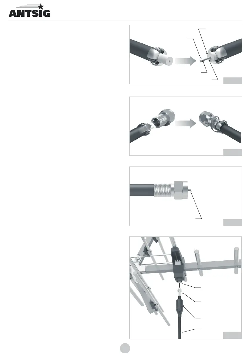
Follow below steps for coaxial cable connection:
1. Remove cable boot and RG6 male F-connector
provided from the sealed poly bag.
2. Slide the cable boot down the coaxial cable and
fit the RG6 male F-connector to the end of the cable
(Follow steps in figures 4a - 4c).
3. Pull enough cable to reach the balun housing.
4. Remove the dust cap from the balun housing
and screw on RG6 male F-connector to the balun
housing. Do not overtighten.
5. Slide the cable boot up the cable onto the balun
housing to cover the F-connector (See figure 4d).
Make sure you have a drip loop in the cable before
finalising the installation, as this allows the water to
run down the cable and “drip” off the loop as shown
on figure 3d.
*Cable runs should be made as short and as even
in length.
Splitting the signal:
When splitting the signal it is beneficial to make
splits as evenly as possible, i.e. in a central location.
Note: A splitter splits the signal to the outputs
regardless of the connections made .i.e. A 4 to 1
splitter will always give a ¼ of the power at each
output, even if you only connect 1 TV.
Consider using a distribution amplifier if you
need to split a weak signal into more than 2 ways,
(See option 2 in figure 5).
Note: electronic amplifiers require a good quality
signal as an input to ensure a good quality signal
is output – the closer to the antenna the better-
therefore it is recommended that distribution
amplifiers be installed within your roof cavity.
Antenna Boom
RG6 Male
F-connector
Female
F-connector
Fig.4d
Fig.04a
Core
Conductor
10mm
6mm
Dielectric
Fig.4b
Trim to 3mm
Fig.4c
6
Strip Cable
Twist On
Boot
Coaxial
Cable
 Loading...