EasyManua.ls Logo

Antunes Controls JD-2 User Manual

Antunes Controls JD-2
4 pages
To Next Page IconTo Next Page
Page #1 background imageLoading...
Page #1 background image
Installation Information
Air Flow Interlocking Safety Switches
Specifications
Ranges
BLUE .07” to 1.7” W.C.
(2 mm to 43 mm W.C.)
GREY 0.1” to 4” W.C.
(3 mm to 102 mm W.C.)
PURPLE 0.1” to 10” W.C.
(3 mm to 250 mm W.C.)
RED 0.1” to 24” W.C.
(3 mm to 600 mm W.C.)
ORANGE 5” to 35” W.C.
(125 mm to 875 mm W.C.)
Maximum Operating Pressure: 35” Water Column
Maximum Pressure Surge: 3 PSIG
Maximum Ambient Operating Temperature:
+140° F (+60° C)
Minimum Ambient Operating Temperature:
-20°F (-93° C)
Model JD-2
Model - JD-2
JD2I 1010801015 01/04
R
L
R
L
R
L
Please read this instruction sheet carefully to assure
correct installation. This equipment must be installed
only by a licensed electrician who is experienced
with combustion safeguard control systems and
understands the functions of an interlocking switch
such as gas pressure switches. Prior to being put
into operation in conjunction with the combustion
safeguard systems, all switches should be tested
for proper range setting and proper wiring. Check
piping connections and switch housing for leaks
with a soap bubble test. All exhaust fans and
blowers should be inspected and checked for
proper rotation prior to starting up. If you have any
problems or questions, phone, fax, email or write to
the manufacturer, Antunes Controls.
Question and Answer IconNeed help?

Do you have a question about the Antunes Controls JD-2 and is the answer not in the manual?

Antunes Controls JD-2 Specifications

General IconGeneral
BrandAntunes Controls
ModelJD-2
CategorySwitch
LanguageEnglish

Summary

Installation Information

Air Flow Interlocking Safety Switches

Overview of the Model JD-2 safety switches, including their purpose and application.

Specifications

Detailed technical specifications including ranges, operating pressure, and temperature limits.

Safety and Installation Guidance

Crucial instructions for correct installation, testing, and safe operation of the switch.

Product Dimensions

Dimensions and Diagrams

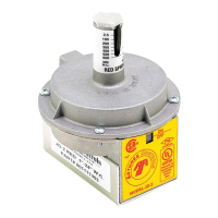
Visual representation of the switch with key dimensions and features for installation planning.

Installation and Electrical Details

Installation Overview and Approvals

Highlights the switch's quality, ease of installation, and UL/FM approvals.

Electrical Ratings and Wiring

Specifies voltage, amperage, horsepower ratings, and field wiring requirements.

Mounting and Air Connections

Mounting Instructions

Guidance on how to mount the switch, including optional brackets and orientation.

Air Connections and Tubing

Recommendations for tubing, pipe size, and air supply connection methods.

Application Diagrams

Illustrations showing connections for differential, vacuum only, and pressure only applications.

Terminal Connections

Terminal Configurations

Details on how terminals connect based on indicator position (Off/On).

Warranty and Liability

Limitation of Liability

Defines the extent of seller's liability regarding product performance and damages.

Product Warranty

Outlines the terms, conditions, and exclusions of the product warranty.