EasyManua.ls Logo

Anywire B2G78-PN1 - Page 33

Default Icon
58 pages
Print Icon
To Next Page IconTo Next Page
To Previous Page IconTo Previous Page
Loading...
I/O data
5-7
5.1.7. I-address/Q-address assignment
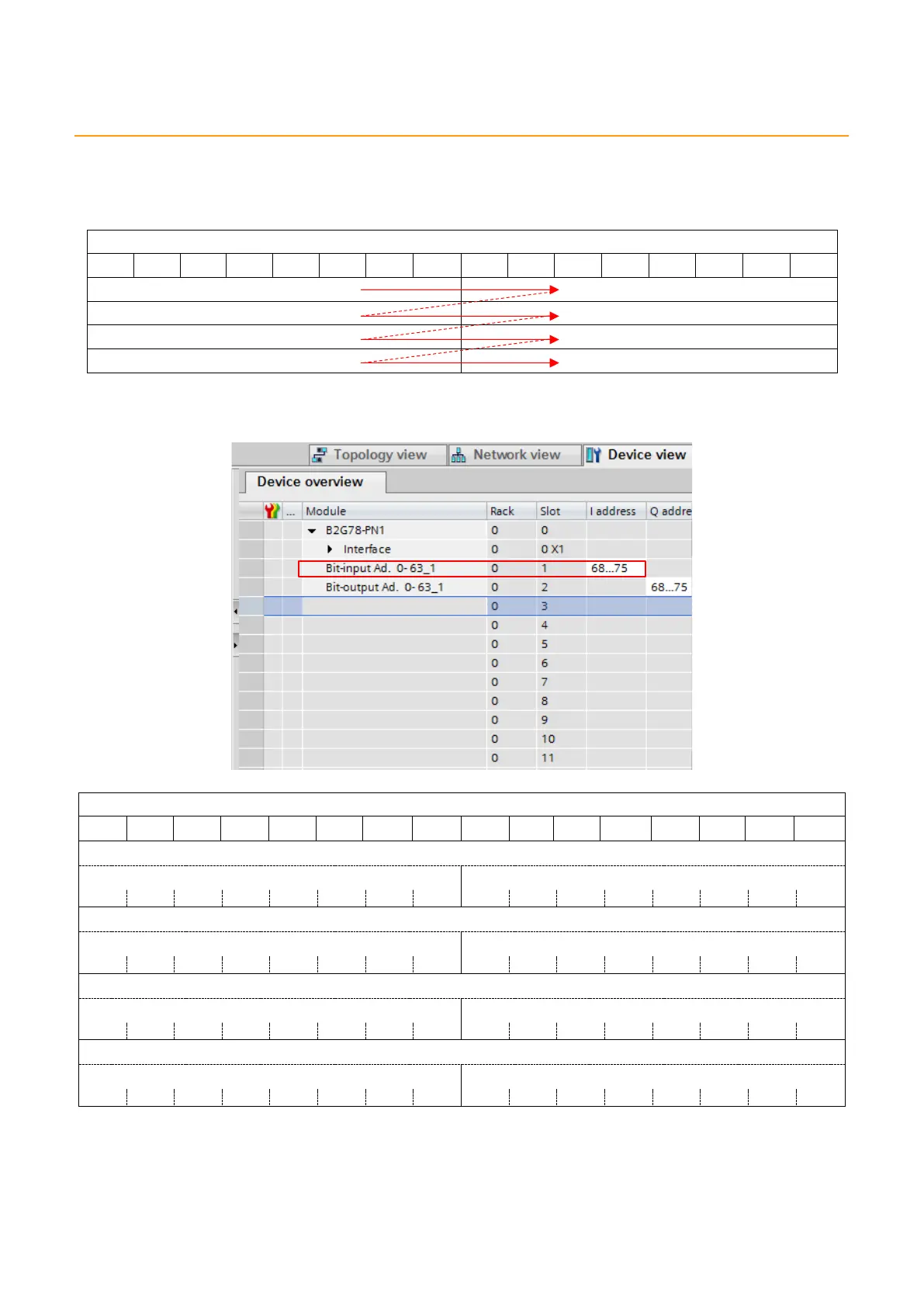
In SIEMENS PLC I-address and Q-address settings, b8 to b15 of ASLINK bit positions are assigned
before b0 to b7.
ASLINK bit position
b15
b14
b13
b12
b11
b10
b9
b8
b7
b6
b5
b4
b3
b2
b1
b0
Example) When “Bit-input Ad. 0-63” is I-address “68…75”, as shown below
Bit-input Ad.0-63
b15
b14
b13
b12
b11
b10
b9
b8
b7
b6
b5
b4
b3
b2
b1
b0
%IW68
%IB68
%IB69
%I68.7
%I68.6
%I68.5
%I68.4
%I68.3
%I68.2
%I68.1
%I68.0
%I69.7
%I69.6
%I69.5
%I69.4
%I69.3
%I69.2
%I69.1
%I69.0
%IW70
%IB70
%IB71
%I70.7
%I70.6
%I70.5
%I70.4
%I70.3
%I70.2
%I70.1
%I70.0
%I71.7
%I71.6
%I71.5
%I71.4
%I71.3
%I71.2
%I71.1
%I71.0
%IW72
%IB72
%IB73
%I72.7
%I72.6
%I72.5
%I72.4
%I72.3
%I72.2
%I72.1
%I72.0
%I73.7
%I73.6
%I73.5
%I73.4
%I73.3
%I73.2
%I73.1
%I73.0
%IW74
%IB74
%IB75
%I74.7
%I74.6
%I74.5
%I74.4
%I74.3
%I74.2
%I74.1
%I74.0
%I75.7
%I75.6
%I75.5
%I75.4
%I75.3
%I75.2
%I75.1
%I75.0
Accordingly, when “Switch0” tag is attached to ASLINK bit input address “0”, and “Switch63” tag is
attached to ASLINK bit input address “63”, these settings are as follows: