SERVO / ESC TEST MODE
Servo 5V Power IN
pack or 5V UBEC module power supply
use of power supply is the nickel battery port
mode
matching of the working voltage parameter with the actuator
power supply to the CellMeter8 with the power supply of the steering gear
and the working voltage of the steering gear is not matched
supply voltage to confirm correct
Servo port on the left co
the direction of the signal to the port
Long press CELL
the default for the servo test mode
Adjust PPM knob to change the duty cycle of the PPM signal to achieve the manual test of the servo
function
param
CELL
signal test mode
large
Adjust PPM knob to change the PPM signal to change the speed of the air ratio
automatic test and test for aging
Short press CELL
mode to enter the midpoint signal
ESC TEST MODE
Connect the 3 hole plug of the Servo to the Test PPM OUT ESC port on the left corner of the
CellMeter8
port
power supply
PPM signal output mode
signal adjustment method
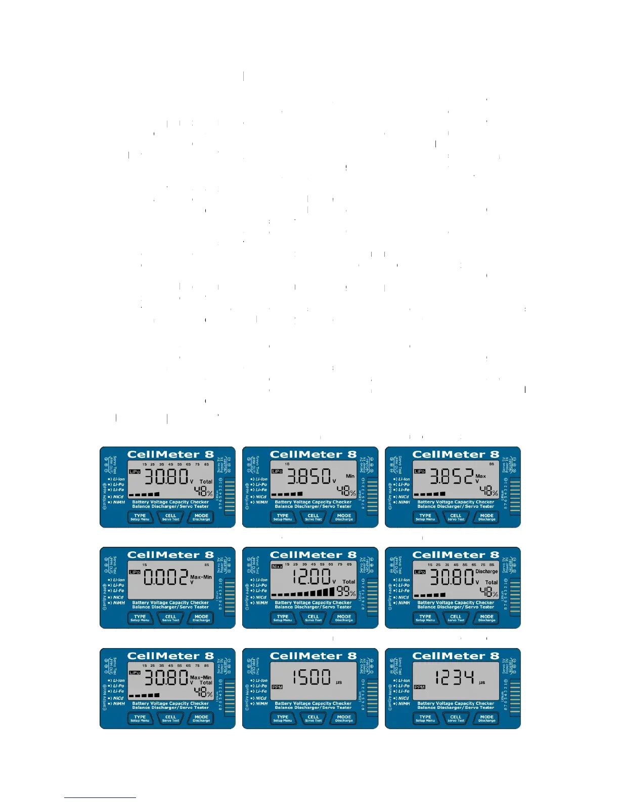
FUNCTIONAL INTERFACE DISPLAY GRAPH
Total voltage of lithium battery
Lithium battery balance mode
SERVO / ESC TEST MODE
Servo 5V Power IN
pack or 5V UBEC module power supply
use of power supply is the nickel battery port
mode
matching of the working voltage parameter with the actuator
power supply to the CellMeter8 with the power supply of the steering gear
and the working voltage of the steering gear is not matched
supply voltage to confirm correct
Servo port on the left co
the direction of the signal to the port
Long press CELL
the default for the servo test mode
Adjust PPM knob to change the duty cycle of the PPM signal to achieve the manual test of the servo
function
param
CELL
signal test mode
large,
Adjust PPM knob to change the PPM signal to change the speed of the air ratio
automatic test and test for aging
Short press CELL
mode to enter the midpoint signal
ESC TEST MODE
Connect the 3 hole plug of the Servo to the Test PPM OUT ESC port on the left corner of the
CellMeter8
port
(
power supply
PPM signal output mode
signal adjustment method
FUNCTIONAL INTERFACE DISPLAY GRAPH
Total voltage of lithium battery
Max
Lithium battery balance mode
SERVO / ESC TEST MODE
Servo 5V Power IN
pack or 5V UBEC module power supply
use of power supply is the nickel battery port
mode
At this
matching of the working voltage parameter with the actuator
power supply to the CellMeter8 with the power supply of the steering gear
and the working voltage of the steering gear is not matched
supply voltage to confirm correct
Servo port on the left co
the direction of the signal to the port
Long press CELL
the default for the servo test mode
Adjust PPM knob to change the duty cycle of the PPM signal to achieve the manual test of the servo
function.
parameters of the servo testing range
CELL
Test Servo
signal test mode
,Changes in the large to small
Adjust PPM knob to change the PPM signal to change the speed of the air ratio
automatic test and test for aging
Short press CELL
mode to enter the midpoint signal
ESC TEST MODE
Connect the 3 hole plug of the Servo to the Test PPM OUT ESC port on the left corner of the
CellMeter8
(CellMeter8 power supply works by the electronic speed regulator for the internal BEC supply 5V
power supply
PPM signal output mode
signal adjustment method
FUNCTIONAL INTERFACE DISPLAY GRAPH
Total voltage of lithium battery
Max
Min of lithium battery
Lithium battery balance mode
SERVO / ESC TEST MODE
Servo 5V Power IN
pack or 5V UBEC module power supply
use of power supply is the nickel battery port
At this
matching of the working voltage parameter with the actuator
power supply to the CellMeter8 with the power supply of the steering gear
and the working voltage of the steering gear is not matched
supply voltage to confirm correct
Servo port on the left co
the direction of the signal to the port
Long press CELL
the default for the servo test mode
Adjust PPM knob to change the duty cycle of the PPM signal to achieve the manual test of the servo
.The adjustment range is 500~2500uS or 1000~2000uS
eters of the servo testing range
Test Servo
signal test mode
Changes in the large to small
Adjust PPM knob to change the PPM signal to change the speed of the air ratio
automatic test and test for aging
Short press CELL
mode to enter the midpoint signal
ESC TEST MODE
Connect the 3 hole plug of the Servo to the Test PPM OUT ESC port on the left corner of the
CellMeter8,
CellMeter8 power supply works by the electronic speed regulator for the internal BEC supply 5V
power supply
PPM signal output mode
signal adjustment method
FUNCTIONAL INTERFACE DISPLAY GRAPH
Total voltage of lithium battery
Min of lithium battery
Lithium battery balance mode
SERVO / ESC TEST MODE
Servo 5V Power IN
pack or 5V UBEC module power supply
use of power supply is the nickel battery port
At this point
matching of the working voltage parameter with the actuator
power supply to the CellMeter8 with the power supply of the steering gear
and the working voltage of the steering gear is not matched
supply voltage to confirm correct
Servo port on the left co
the direction of the signal to the port
Long press CELL
the default for the servo test mode
Adjust PPM knob to change the duty cycle of the PPM signal to achieve the manual test of the servo
The adjustment range is 500~2500uS or 1000~2000uS
eters of the servo testing range
Test Servo
signal test mode
Changes in the large to small
Adjust PPM knob to change the PPM signal to change the speed of the air ratio
automatic test and test for aging
Short press CELL
mode to enter the midpoint signal
ESC TEST MODE
Connect the 3 hole plug of the Servo to the Test PPM OUT ESC port on the left corner of the
,Correct insertion of the
CellMeter8 power supply works by the electronic speed regulator for the internal BEC supply 5V
power supply
No connection to other power supply
PPM signal output mode
signal adjustment method
FUNCTIONAL INTERFACE DISPLAY GRAPH
Total voltage of lithium battery
Min of lithium battery
Lithium battery balance mode
SERVO / ESC TEST MODE
Servo 5V Power IN
pack or 5V UBEC module power supply
use of power supply is the nickel battery port
point
matching of the working voltage parameter with the actuator
power supply to the CellMeter8 with the power supply of the steering gear
and the working voltage of the steering gear is not matched
supply voltage to confirm correct
Servo port on the left co
the direction of the signal to the port
Long press CELL
the default for the servo test mode
Adjust PPM knob to change the duty cycle of the PPM signal to achieve the manual test of the servo
The adjustment range is 500~2500uS or 1000~2000uS
eters of the servo testing range
Test Servo
signal test mode
Changes in the large to small
Adjust PPM knob to change the PPM signal to change the speed of the air ratio
automatic test and test for aging
Short press CELL
mode to enter the midpoint signal
ESC TEST MODE
Connect the 3 hole plug of the Servo to the Test PPM OUT ESC port on the left corner of the
Correct insertion of the
CellMeter8 power supply works by the electronic speed regulator for the internal BEC supply 5V
No connection to other power supply
PPM signal output mode
signal adjustment method
FUNCTIONAL INTERFACE DISPLAY GRAPH
Total voltage of lithium battery
Min of lithium battery
Lithium battery balance mode
SERVO / ESC TEST MODE
Servo 5V Power IN(
pack or 5V UBEC module power supply
use of power supply is the nickel battery port
point
the voltage of the battery is confirmed by the screen to confirm whether the
matching of the working voltage parameter with the actuator
power supply to the CellMeter8 with the power supply of the steering gear
and the working voltage of the steering gear is not matched
supply voltage to confirm correct
Servo port on the left co
the direction of the signal to the port
Long press CELL
Test Servo
the default for the servo test mode
Adjust PPM knob to change the duty cycle of the PPM signal to achieve the manual test of the servo
The adjustment range is 500~2500uS or 1000~2000uS
eters of the servo testing range
Test Servo
In this mode the PPM signal is accounted for by the automatic small to
Changes in the large to small
Adjust PPM knob to change the PPM signal to change the speed of the air ratio
automatic test and test for aging
Short press CELL
Test Servo
mode to enter the midpoint signal
ESC TEST MODE
Connect the 3 hole plug of the Servo to the Test PPM OUT ESC port on the left corner of the
Correct insertion of the
CellMeter8 power supply works by the electronic speed regulator for the internal BEC supply 5V
No connection to other power supply
PPM signal output mode
signal adjustment method
FUNCTIONAL INTERFACE DISPLAY GRAPH
Total voltage of lithium battery
Min of lithium battery
Lithium battery balance mode
SERVO / ESC TEST MODE
(NiCd/MH
pack or 5V UBEC module power supply
use of power supply is the nickel battery port
the voltage of the battery is confirmed by the screen to confirm whether the
matching of the working voltage parameter with the actuator
power supply to the CellMeter8 with the power supply of the steering gear
and the working voltage of the steering gear is not matched
supply voltage to confirm correct
Servo port on the left co
the direction of the signal to the port
Test Servo
the default for the servo test mode
Adjust PPM knob to change the duty cycle of the PPM signal to achieve the manual test of the servo
The adjustment range is 500~2500uS or 1000~2000uS
eters of the servo testing range
or MODE
In this mode the PPM signal is accounted for by the automatic small to
Changes in the large to small
Adjust PPM knob to change the PPM signal to change the speed of the air ratio
automatic test and test for aging
Test Servo
mode to enter the midpoint signal
ESC TEST MODE
Connect the 3 hole plug of the Servo to the Test PPM OUT ESC port on the left corner of the
Correct insertion of the
CellMeter8 power supply works by the electronic speed regulator for the internal BEC supply 5V
No connection to other power supply
PPM signal output mode
signal adjustment method
FUNCTIONAL INTERFACE DISPLAY GRAPH
Total voltage of lithium battery
Min of lithium battery
Lithium battery balance mode
SERVO / ESC TEST MODE
NiCd/MH
pack or 5V UBEC module power supply
use of power supply is the nickel battery port
the voltage of the battery is confirmed by the screen to confirm whether the
matching of the working voltage parameter with the actuator
power supply to the CellMeter8 with the power supply of the steering gear
and the working voltage of the steering gear is not matched
supply voltage to confirm correct
Servo port on the left corner of the CellMeter8
the direction of the signal to the port
Test Servo
the default for the servo test mode
Adjust PPM knob to change the duty cycle of the PPM signal to achieve the manual test of the servo
The adjustment range is 500~2500uS or 1000~2000uS
eters of the servo testing range
or MODE
In this mode the PPM signal is accounted for by the automatic small to
Changes in the large to small
Adjust PPM knob to change the PPM signal to change the speed of the air ratio
automatic test and test for aging
Test Servo
mode to enter the midpoint signal
ESC TEST MODE
Connect the 3 hole plug of the Servo to the Test PPM OUT ESC port on the left corner of the
Correct insertion of the
CellMeter8 power supply works by the electronic speed regulator for the internal BEC supply 5V
No connection to other power supply
PPM signal output mode
PPM signal output duty cycle adjustment method and servo test mode PPM
signal adjustment method
FUNCTIONAL INTERFACE DISPLAY GRAPH
Total voltage of lithium battery
Min of lithium battery
Lithium battery balance mode
SERVO / ESC TEST MODE
NiCd/MH
pack or 5V UBEC module power supply
use of power supply is the nickel battery port
the voltage of the battery is confirmed by the screen to confirm whether the
matching of the working voltage parameter with the actuator
power supply to the CellMeter8 with the power supply of the steering gear
and the working voltage of the steering gear is not matched
supply voltage to confirm correct
rner of the CellMeter8
the direction of the signal to the port
Test Servo
the default for the servo test mode
Adjust PPM knob to change the duty cycle of the PPM signal to achieve the manual test of the servo
The adjustment range is 500~2500uS or 1000~2000uS
eters of the servo testing range
or MODE (
In this mode the PPM signal is accounted for by the automatic small to
Changes in the large to small
Adjust PPM knob to change the PPM signal to change the speed of the air ratio
automatic test and test for aging
Test Servo
mode to enter the midpoint signal
Connect the 3 hole plug of the Servo to the Test PPM OUT ESC port on the left corner of the
Correct insertion of the
CellMeter8 power supply works by the electronic speed regulator for the internal BEC supply 5V
No connection to other power supply
PPM signal output duty cycle adjustment method and servo test mode PPM
.
FUNCTIONAL INTERFACE DISPLAY GRAPH
Total voltage of lithium battery
Lithium battery balance mode
SERVO / ESC TEST MODE
NiCd/MH
port connection
pack or 5V UBEC module power supply
use of power supply is the nickel battery port
the voltage of the battery is confirmed by the screen to confirm whether the
matching of the working voltage parameter with the actuator
power supply to the CellMeter8 with the power supply of the steering gear
and the working voltage of the steering gear is not matched
supply voltage to confirm correct
rner of the CellMeter8
the direction of the signal to the port
Test Servo
button to enter the steering gear test mode
the default for the servo test mode
Adjust PPM knob to change the duty cycle of the PPM signal to achieve the manual test of the servo
The adjustment range is 500~2500uS or 1000~2000uS
eters of the servo testing range
(Discharge
In this mode the PPM signal is accounted for by the automatic small to
Changes in the large to small
Adjust PPM knob to change the PPM signal to change the speed of the air ratio
automatic test and test for aging.
Test Servo
or MODE
mode to enter the midpoint signal
Connect the 3 hole plug of the Servo to the Test PPM OUT ESC port on the left corner of the
Correct insertion of the
CellMeter8 power supply works by the electronic speed regulator for the internal BEC supply 5V
No connection to other power supply
PPM signal output duty cycle adjustment method and servo test mode PPM
FUNCTIONAL INTERFACE DISPLAY GRAPH
Lithium battery balance mode
SERVO / ESC TEST MODE
port connection
pack or 5V UBEC module power supply
use of power supply is the nickel battery port
the voltage of the battery is confirmed by the screen to confirm whether the
matching of the working voltage parameter with the actuator
power supply to the CellMeter8 with the power supply of the steering gear
and the working voltage of the steering gear is not matched
supply voltage to confirm correct
Connect the 3 hole plug of the steering gear to the Test PPM OUT
rner of the CellMeter8
the direction of the signal to the port
button to enter the steering gear test mode
the default for the servo test mode,
Adjust PPM knob to change the duty cycle of the PPM signal to achieve the manual test of the servo
The adjustment range is 500~2500uS or 1000~2000uS
eters of the servo testing range
Discharge
In this mode the PPM signal is accounted for by the automatic small to
Changes in the large to small
Adjust PPM knob to change the PPM signal to change the speed of the air ratio
.
or MODE
mode to enter the midpoint signal
The duty cycle of the PPM signal is 1500uS
Connect the 3 hole plug of the Servo to the Test PPM OUT ESC port on the left corner of the
Correct insertion of the
CellMeter8 power supply works by the electronic speed regulator for the internal BEC supply 5V
No connection to other power supply
PPM signal output duty cycle adjustment method and servo test mode PPM
FUNCTIONAL INTERFACE DISPLAY GRAPH
Lithium battery Minimum voltage
Total voltage of N
Lithium battery balance mode
SERVO / ESC TEST MODE
port connection
pack or 5V UBEC module power supply
use of power supply is the nickel battery port
the voltage of the battery is confirmed by the screen to confirm whether the
matching of the working voltage parameter with the actuator
power supply to the CellMeter8 with the power supply of the steering gear
and the working voltage of the steering gear is not matched
Connect the 3 hole plug of the steering gear to the Test PPM OUT
rner of the CellMeter8
the direction of the signal to the port
button to enter the steering gear test mode
,That is
Adjust PPM knob to change the duty cycle of the PPM signal to achieve the manual test of the servo
The adjustment range is 500~2500uS or 1000~2000uS
eters of the servo testing range
Discharge
In this mode the PPM signal is accounted for by the automatic small to
Changes in the large to small cycles
Adjust PPM knob to change the PPM signal to change the speed of the air ratio
or MODE
The duty cycle of the PPM signal is 1500uS
Connect the 3 hole plug of the Servo to the Test PPM OUT ESC port on the left corner of the
Correct insertion of the positive and negative poles and the direction of the signal to the
CellMeter8 power supply works by the electronic speed regulator for the internal BEC supply 5V
No connection to other power supply
PPM signal output duty cycle adjustment method and servo test mode PPM
FUNCTIONAL INTERFACE DISPLAY GRAPH
Lithium battery Minimum voltage
Total voltage of N
Servo midpoint test mode
SERVO / ESC TEST MODE
port connection
pack or 5V UBEC module power supply
After power supply connection
use of power supply is the nickel battery port
the voltage of the battery is confirmed by the screen to confirm whether the
matching of the working voltage parameter with the actuator
power supply to the CellMeter8 with the power supply of the steering gear
and the working voltage of the steering gear is not matched
Connect the 3 hole plug of the steering gear to the Test PPM OUT
rner of the CellMeter8
button to enter the steering gear test mode
That is
Adjust PPM knob to change the duty cycle of the PPM signal to achieve the manual test of the servo
The adjustment range is 500~2500uS or 1000~2000uS
Discharge
button is short in the manual mode
In this mode the PPM signal is accounted for by the automatic small to
cycles
Adjust PPM knob to change the PPM signal to change the speed of the air ratio
or MODE
The duty cycle of the PPM signal is 1500uS
Connect the 3 hole plug of the Servo to the Test PPM OUT ESC port on the left corner of the
positive and negative poles and the direction of the signal to the
CellMeter8 power supply works by the electronic speed regulator for the internal BEC supply 5V
No connection to other power supply
PPM signal output duty cycle adjustment method and servo test mode PPM
FUNCTIONAL INTERFACE DISPLAY GRAPH
Lithium battery Minimum voltage
Total voltage of N
Servo midpoint test mode
port connection
After power supply connection
use of power supply is the nickel battery port
the voltage of the battery is confirmed by the screen to confirm whether the
matching of the working voltage parameter with the actuator
power supply to the CellMeter8 with the power supply of the steering gear
and the working voltage of the steering gear is not matched
Connect the 3 hole plug of the steering gear to the Test PPM OUT
rner of the CellMeter8
button to enter the steering gear test mode
That is
by the user to manually adjust the left of the CellMeter8
Adjust PPM knob to change the duty cycle of the PPM signal to achieve the manual test of the servo
The adjustment range is 500~2500uS or 1000~2000uS
button is short in the manual mode
In this mode the PPM signal is accounted for by the automatic small to
cycles
By the user to manually adjust the left of the CellMeter8
Adjust PPM knob to change the PPM signal to change the speed of the air ratio
or MODE
Discharge
The duty cycle of the PPM signal is 1500uS
Connect the 3 hole plug of the Servo to the Test PPM OUT ESC port on the left corner of the
positive and negative poles and the direction of the signal to the
CellMeter8 power supply works by the electronic speed regulator for the internal BEC supply 5V
No connection to other power supply
PPM signal output duty cycle adjustment method and servo test mode PPM
FUNCTIONAL INTERFACE DISPLAY GRAPH
Lithium battery Minimum voltage
Total voltage of N
Servo midpoint test mode
port connection power supply 5~6V
After power supply connection
use of power supply is the nickel battery port
the voltage of the battery is confirmed by the screen to confirm whether the
matching of the working voltage parameter with the actuator
power supply to the CellMeter8 with the power supply of the steering gear
and the working voltage of the steering gear is not matched
Connect the 3 hole plug of the steering gear to the Test PPM OUT
rner of the CellMeter8
Correct insertion of the positive and negative poles and
button to enter the steering gear test mode
by the user to manually adjust the left of the CellMeter8
Adjust PPM knob to change the duty cycle of the PPM signal to achieve the manual test of the servo
The adjustment range is 500~2500uS or 1000~2000uS
button is short in the manual mode
In this mode the PPM signal is accounted for by the automatic small to
By the user to manually adjust the left of the CellMeter8
Adjust PPM knob to change the PPM signal to change the speed of the air ratio
Discharge
The duty cycle of the PPM signal is 1500uS
Connect the 3 hole plug of the Servo to the Test PPM OUT ESC port on the left corner of the
positive and negative poles and the direction of the signal to the
CellMeter8 power supply works by the electronic speed regulator for the internal BEC supply 5V
No connection to other power supply
PPM signal output duty cycle adjustment method and servo test mode PPM
FUNCTIONAL INTERFACE DISPLAY GRAPH
Lithium battery Minimum voltage
Total voltage of N
Servo midpoint test mode
power supply 5~6V
After power supply connection
use of power supply is the nickel battery port
Therefore
the voltage of the battery is confirmed by the screen to confirm whether the
matching of the working voltage parameter with the actuator
power supply to the CellMeter8 with the power supply of the steering gear
and the working voltage of the steering gear is not matched
Connect the 3 hole plug of the steering gear to the Test PPM OUT
Correct insertion of the positive and negative poles and
button to enter the steering gear test mode
by the user to manually adjust the left of the CellMeter8
Adjust PPM knob to change the duty cycle of the PPM signal to achieve the manual test of the servo
The adjustment range is 500~2500uS or 1000~2000uS
button is short in the manual mode
In this mode the PPM signal is accounted for by the automatic small to
By the user to manually adjust the left of the CellMeter8
Adjust PPM knob to change the PPM signal to change the speed of the air ratio
Discharge
The duty cycle of the PPM signal is 1500uS
Connect the 3 hole plug of the Servo to the Test PPM OUT ESC port on the left corner of the
positive and negative poles and the direction of the signal to the
CellMeter8 power supply works by the electronic speed regulator for the internal BEC supply 5V
No connection to other power supply.
PPM signal output duty cycle adjustment method and servo test mode PPM
FUNCTIONAL INTERFACE DISPLAY GRAPH
Lithium battery Minimum voltage
power supply 5~6V
After power supply connection
Therefore
the voltage of the battery is confirmed by the screen to confirm whether the
matching of the working voltage parameter with the actuator
power supply to the CellMeter8 with the power supply of the steering gear
and the working voltage of the steering gear is not matched
Connect the 3 hole plug of the steering gear to the Test PPM OUT
Correct insertion of the positive and negative poles and
button to enter the steering gear test mode
by the user to manually adjust the left of the CellMeter8
Adjust PPM knob to change the duty cycle of the PPM signal to achieve the manual test of the servo
The adjustment range is 500~2500uS or 1000~2000uS
button is short in the manual mode
In this mode the PPM signal is accounted for by the automatic small to
By the user to manually adjust the left of the CellMeter8
Adjust PPM knob to change the PPM signal to change the speed of the air ratio
Discharge)
The duty cycle of the PPM signal is 1500uS
Connect the 3 hole plug of the Servo to the Test PPM OUT ESC port on the left corner of the
positive and negative poles and the direction of the signal to the
CellMeter8 power supply works by the electronic speed regulator for the internal BEC supply 5V
.
Long press CELL
PPM signal output duty cycle adjustment method and servo test mode PPM
FUNCTIONAL INTERFACE DISPLAY GRAPH
Lithium battery Minimum voltage
ickel
Servo midpoint test mode
power supply 5~6V
After power supply connection
Therefore
the voltage of the battery is confirmed by the screen to confirm whether the
matching of the working voltage parameter with the actuator
power supply to the CellMeter8 with the power supply of the steering gear
and the working voltage of the steering gear is not matched
Connect the 3 hole plug of the steering gear to the Test PPM OUT
Correct insertion of the positive and negative poles and
button to enter the steering gear test mode
by the user to manually adjust the left of the CellMeter8
Adjust PPM knob to change the duty cycle of the PPM signal to achieve the manual test of the servo
The adjustment range is 500~2500uS or 1000~2000uS
button is short in the manual mode
In this mode the PPM signal is accounted for by the automatic small to
By the user to manually adjust the left of the CellMeter8
Adjust PPM knob to change the PPM signal to change the speed of the air ratio
)
button in the a
The duty cycle of the PPM signal is 1500uS
Connect the 3 hole plug of the Servo to the Test PPM OUT ESC port on the left corner of the
positive and negative poles and the direction of the signal to the
CellMeter8 power supply works by the electronic speed regulator for the internal BEC supply 5V
Long press CELL
PPM signal output duty cycle adjustment method and servo test mode PPM
FUNCTIONAL INTERFACE DISPLAY GRAPH
Lithium battery Minimum voltage
ickel
battery
Servo midpoint test mode
power supply 5~6V
After power supply connection
Therefore
the screen is a nickel battery detection
the voltage of the battery is confirmed by the screen to confirm whether the
matching of the working voltage parameter with the actuator
power supply to the CellMeter8 with the power supply of the steering gear
and the working voltage of the steering gear is not matched
It is likely to burn the steering gear
Connect the 3 hole plug of the steering gear to the Test PPM OUT
Correct insertion of the positive and negative poles and
button to enter the steering gear test mode
by the user to manually adjust the left of the CellMeter8
Adjust PPM knob to change the duty cycle of the PPM signal to achieve the manual test of the servo
The adjustment range is 500~2500uS or 1000~2000uS
button is short in the manual mode
In this mode the PPM signal is accounted for by the automatic small to
By the user to manually adjust the left of the CellMeter8
Adjust PPM knob to change the PPM signal to change the speed of the air ratio
button in the a
The duty cycle of the PPM signal is 1500uS
Connect the 3 hole plug of the Servo to the Test PPM OUT ESC port on the left corner of the
positive and negative poles and the direction of the signal to the
CellMeter8 power supply works by the electronic speed regulator for the internal BEC supply 5V
Long press CELL
PPM signal output duty cycle adjustment method and servo test mode PPM
FUNCTIONAL INTERFACE DISPLAY GRAPH
Lithium battery Minimum voltage
battery
Servo midpoint test mode
power supply 5~6V
After power supply connection
the screen is a nickel battery detection
the voltage of the battery is confirmed by the screen to confirm whether the
matching of the working voltage parameter with the actuator
If no match is required to replace the
power supply to the CellMeter8 with the power supply of the steering gear
It is likely to burn the steering gear
Connect the 3 hole plug of the steering gear to the Test PPM OUT
Correct insertion of the positive and negative poles and
button to enter the steering gear test mode
by the user to manually adjust the left of the CellMeter8
Adjust PPM knob to change the duty cycle of the PPM signal to achieve the manual test of the servo
The adjustment range is 500~2500uS or 1000~2000uS
button is short in the manual mode
In this mode the PPM signal is accounted for by the automatic small to
By the user to manually adjust the left of the CellMeter8
Adjust PPM knob to change the PPM signal to change the speed of the air ratio
button in the a
The duty cycle of the PPM signal is 1500uS
Connect the 3 hole plug of the Servo to the Test PPM OUT ESC port on the left corner of the
positive and negative poles and the direction of the signal to the
CellMeter8 power supply works by the electronic speed regulator for the internal BEC supply 5V
Long press CELL
PPM signal output duty cycle adjustment method and servo test mode PPM
FUNCTIONAL INTERFACE DISPLAY GRAPH
Lithium battery Minimum voltage
battery
power supply 5~6V
After power supply connection
the screen is a nickel battery detection
the voltage of the battery is confirmed by the screen to confirm whether the
If no match is required to replace the
power supply to the CellMeter8 with the power supply of the steering gear
It is likely to burn the steering gear
Connect the 3 hole plug of the steering gear to the Test PPM OUT
Correct insertion of the positive and negative poles and
button to enter the steering gear test mode
by the user to manually adjust the left of the CellMeter8
Adjust PPM knob to change the duty cycle of the PPM signal to achieve the manual test of the servo
The adjustment range is 500~2500uS or 1000~2000uS
button is short in the manual mode
In this mode the PPM signal is accounted for by the automatic small to
By the user to manually adjust the left of the CellMeter8
Adjust PPM knob to change the PPM signal to change the speed of the air ratio
button in the a
The duty cycle of the PPM signal is 1500uS
Connect the 3 hole plug of the Servo to the Test PPM OUT ESC port on the left corner of the
positive and negative poles and the direction of the signal to the
CellMeter8 power supply works by the electronic speed regulator for the internal BEC supply 5V
Long press CELL
PPM signal output duty cycle adjustment method and servo test mode PPM
FUNCTIONAL INTERFACE DISPLAY GRAPH
You can use NiCd/MH 4S battery
After power supply connection
the screen is a nickel battery detection
the voltage of the battery is confirmed by the screen to confirm whether the
If no match is required to replace the
power supply to the CellMeter8 with the power supply of the steering gear
It is likely to burn the steering gear
Connect the 3 hole plug of the steering gear to the Test PPM OUT
Correct insertion of the positive and negative poles and
button to enter the steering gear test mode
by the user to manually adjust the left of the CellMeter8
Adjust PPM knob to change the duty cycle of the PPM signal to achieve the manual test of the servo
The adjustment range is 500~2500uS or 1000~2000uS
button is short in the manual mode
In this mode the PPM signal is accounted for by the automatic small to
By the user to manually adjust the left of the CellMeter8
Adjust PPM knob to change the PPM signal to change the speed of the air ratio
button in the a
The duty cycle of the PPM signal is 1500uS
Connect the 3 hole plug of the Servo to the Test PPM OUT ESC port on the left corner of the
positive and negative poles and the direction of the signal to the
CellMeter8 power supply works by the electronic speed regulator for the internal BEC supply 5V
Long press CELL
PPM signal output duty cycle adjustment method and servo test mode PPM
Lithium battery maximum voltage
Lithium battery discharge mode
You can use NiCd/MH 4S battery
After power supply connection
CellMeter 8 start working
the screen is a nickel battery detection
the voltage of the battery is confirmed by the screen to confirm whether the
If no match is required to replace the
power supply to the CellMeter8 with the power supply of the steering gear
It is likely to burn the steering gear
Connect the 3 hole plug of the steering gear to the Test PPM OUT
Correct insertion of the positive and negative poles and
button to enter the steering gear test mode
by the user to manually adjust the left of the CellMeter8
Adjust PPM knob to change the duty cycle of the PPM signal to achieve the manual test of the servo
The adjustment range is 500~2500uS or 1000~2000uS
which is determined by the
button is short in the manual mode
In this mode the PPM signal is accounted for by the automatic small to
By the user to manually adjust the left of the CellMeter8
Adjust PPM knob to change the PPM signal to change the speed of the air ratio
button in the automatic signal test mode
The duty cycle of the PPM signal is 1500uS
Connect the 3 hole plug of the Servo to the Test PPM OUT ESC port on the left corner of the
positive and negative poles and the direction of the signal to the
CellMeter8 power supply works by the electronic speed regulator for the internal BEC supply 5V
Long press CELL
Test Servo
PPM signal output duty cycle adjustment method and servo test mode PPM
Lithium battery maximum voltage
Lithium battery discharge mode
You can use NiCd/MH 4S battery
CellMeter 8 start working
the screen is a nickel battery detection
the voltage of the battery is confirmed by the screen to confirm whether the
If no match is required to replace the
power supply to the CellMeter8 with the power supply of the steering gear
Such as the supply voltage
It is likely to burn the steering gear
Connect the 3 hole plug of the steering gear to the Test PPM OUT
Correct insertion of the positive and negative poles and
button to enter the steering gear test mode,
by the user to manually adjust the left of the CellMeter8
Adjust PPM knob to change the duty cycle of the PPM signal to achieve the manual test of the servo
which is determined by the
button is short in the manual mode
In this mode the PPM signal is accounted for by the automatic small to
By the user to manually adjust the left of the CellMeter8
Adjust PPM knob to change the PPM signal to change the speed of the air ratio
utomatic signal test mode
The duty cycle of the PPM signal is 1500uS
Connect the 3 hole plug of the Servo to the Test PPM OUT ESC port on the left corner of the
positive and negative poles and the direction of the signal to the
CellMeter8 power supply works by the electronic speed regulator for the internal BEC supply 5V
Test Servo
PPM signal output duty cycle adjustment method and servo test mode PPM
Lithium battery maximum voltage
Lithium battery discharge mode
Servo
You can use NiCd/MH 4S battery
CellMeter 8 start working
the screen is a nickel battery detection
the voltage of the battery is confirmed by the screen to confirm whether the
If no match is required to replace the
Such as the supply voltage
It is likely to burn the steering gear
Connect the 3 hole plug of the steering gear to the Test PPM OUT
Correct insertion of the positive and negative poles and
,The manual test signal is
by the user to manually adjust the left of the CellMeter8
Adjust PPM knob to change the duty cycle of the PPM signal to achieve the manual test of the servo
which is determined by the
button is short in the manual mode
Enter into the automatic
In this mode the PPM signal is accounted for by the automatic small to
By the user to manually adjust the left of the CellMeter8
Adjust PPM knob to change the PPM signal to change the speed of the air ratio
utomatic signal test mode
The duty cycle of the PPM signal is 1500uS.
Connect the 3 hole plug of the Servo to the Test PPM OUT ESC port on the left corner of the
positive and negative poles and the direction of the signal to the
CellMeter8 power supply works by the electronic speed regulator for the internal BEC supply 5V
Test Servo
PPM signal output duty cycle adjustment method and servo test mode PPM
Lithium battery maximum voltage
Lithium battery discharge mode
Servo manual test mode
You can use NiCd/MH 4S battery
CellMeter 8 start working
the screen is a nickel battery detection
the voltage of the battery is confirmed by the screen to confirm whether the
If no match is required to replace the
Such as the supply voltage
It is likely to burn the steering gear
Connect the 3 hole plug of the steering gear to the Test PPM OUT
Correct insertion of the positive and negative poles and
The manual test signal is
by the user to manually adjust the left of the CellMeter8
Adjust PPM knob to change the duty cycle of the PPM signal to achieve the manual test of the servo
which is determined by the
Enter into the automatic
In this mode the PPM signal is accounted for by the automatic small to
By the user to manually adjust the left of the CellMeter8
Adjust PPM knob to change the PPM signal to change the speed of the air ratio
utomatic signal test mode
.
Connect the 3 hole plug of the Servo to the Test PPM OUT ESC port on the left corner of the
positive and negative poles and the direction of the signal to the
CellMeter8 power supply works by the electronic speed regulator for the internal BEC supply 5V
Test Servo
PPM signal output duty cycle adjustment method and servo test mode PPM
Lithium battery maximum voltage
Lithium battery discharge mode
manual test mode
You can use NiCd/MH 4S battery
CellMeter 8 start working
the screen is a nickel battery detection
the voltage of the battery is confirmed by the screen to confirm whether the
If no match is required to replace the
Such as the supply voltage
It is likely to burn the steering gear
Connect the 3 hole plug of the steering gear to the Test PPM OUT
Correct insertion of the positive and negative poles and
The manual test signal is
by the user to manually adjust the left of the CellMeter8
Adjust PPM knob to change the duty cycle of the PPM signal to achieve the manual test of the servo
which is determined by the
Enter into the automatic
In this mode the PPM signal is accounted for by the automatic small to
By the user to manually adjust the left of the CellMeter8
Adjust PPM knob to change the PPM signal to change the speed of the air ratio
utomatic signal test mode
Connect the 3 hole plug of the Servo to the Test PPM OUT ESC port on the left corner of the
positive and negative poles and the direction of the signal to the
CellMeter8 power supply works by the electronic speed regulator for the internal BEC supply 5V
Test Servo
button to
PPM signal output duty cycle adjustment method and servo test mode PPM
Lithium battery maximum voltage
Lithium battery discharge mode
manual test mode
You can use NiCd/MH 4S battery
CellMeter 8 start working
the screen is a nickel battery detection
the voltage of the battery is confirmed by the screen to confirm whether the
If no match is required to replace the
Such as the supply voltage
It is likely to burn the steering gear
Connect the 3 hole plug of the steering gear to the Test PPM OUT
Correct insertion of the positive and negative poles and
The manual test signal is
by the user to manually adjust the left of the CellMeter8
Adjust PPM knob to change the duty cycle of the PPM signal to achieve the manual test of the servo
which is determined by the
Enter into the automatic
In this mode the PPM signal is accounted for by the automatic small to
By the user to manually adjust the left of the CellMeter8
Adjust PPM knob to change the PPM signal to change the speed of the air ratio
utomatic signal test mode
Connect the 3 hole plug of the Servo to the Test PPM OUT ESC port on the left corner of the
positive and negative poles and the direction of the signal to the
CellMeter8 power supply works by the electronic speed regulator for the internal BEC supply 5V
button to
PPM signal output duty cycle adjustment method and servo test mode PPM
Lithium battery maximum voltage
Lithium battery discharge mode
manual test mode
You can use NiCd/MH 4S battery
CellMeter 8 start working
the screen is a nickel battery detection
the voltage of the battery is confirmed by the screen to confirm whether the
If no match is required to replace the
Such as the supply voltage
It is likely to burn the steering gear
Connect the 3 hole plug of the steering gear to the Test PPM OUT
Correct insertion of the positive and negative poles and
The manual test signal is
by the user to manually adjust the left of the CellMeter8
Adjust PPM knob to change the duty cycle of the PPM signal to achieve the manual test of the servo
which is determined by the
Enter into the automatic
In this mode the PPM signal is accounted for by the automatic small to
By the user to manually adjust the left of the CellMeter8
Adjust PPM knob to change the PPM signal to change the speed of the air ratio
Functions of
utomatic signal test mode
Connect the 3 hole plug of the Servo to the Test PPM OUT ESC port on the left corner of the
positive and negative poles and the direction of the signal to the
CellMeter8 power supply works by the electronic speed regulator for the internal BEC supply 5V
button to
PPM signal output duty cycle adjustment method and servo test mode PPM
Lithium battery maximum voltage
Lithium battery discharge mode
manual test mode
You can use NiCd/MH 4S battery
CellMeter 8 start working
the screen is a nickel battery detection
the voltage of the battery is confirmed by the screen to confirm whether the
If no match is required to replace the
Such as the supply voltage
It is likely to burn the steering gear
Connect the 3 hole plug of the steering gear to the Test PPM OUT
Correct insertion of the positive and negative poles and
The manual test signal is
by the user to manually adjust the left of the CellMeter8
Adjust PPM knob to change the duty cycle of the PPM signal to achieve the manual test of the servo
which is determined by the
Enter into the automatic
In this mode the PPM signal is accounted for by the automatic small to
By the user to manually adjust the left of the CellMeter8
Functions of
utomatic signal test mode
Connect the 3 hole plug of the Servo to the Test PPM OUT ESC port on the left corner of the
positive and negative poles and the direction of the signal to the
CellMeter8 power supply works by the electronic speed regulator for the internal BEC supply 5V
button to
enter the
PPM signal output duty cycle adjustment method and servo test mode PPM
Lithium battery maximum voltage
Lithium battery discharge mode
manual test mode
You can use NiCd/MH 4S battery
CellMeter 8 start working
the screen is a nickel battery detection
the voltage of the battery is confirmed by the screen to confirm whether the
If no match is required to replace the
Such as the supply voltage
It is likely to burn the steering gear
Power
Connect the 3 hole plug of the steering gear to the Test PPM OUT
Correct insertion of the positive and negative poles and
The manual test signal is
by the user to manually adjust the left of the CellMeter8
Adjust PPM knob to change the duty cycle of the PPM signal to achieve the manual test of the servo
which is determined by the
Enter into the automatic
In this mode the PPM signal is accounted for by the automatic small to
By the user to manually adjust the left of the CellMeter8
Functions of
utomatic signal test mode,
Connect the 3 hole plug of the Servo to the Test PPM OUT ESC port on the left corner of the
positive and negative poles and the direction of the signal to the
CellMeter8 power supply works by the electronic speed regulator for the internal BEC supply 5V
enter the
PPM signal output duty cycle adjustment method and servo test mode PPM
Lithium battery maximum voltage
Lithium battery discharge mode
You can use NiCd/MH 4S battery
CellMeter 8 start working
The
the screen is a nickel battery detection
the voltage of the battery is confirmed by the screen to confirm whether the
If no match is required to replace the
Such as the supply voltage
Power
Connect the 3 hole plug of the steering gear to the Test PPM OUT
Correct insertion of the positive and negative poles and
The manual test signal is
by the user to manually adjust the left of the CellMeter8
Adjust PPM knob to change the duty cycle of the PPM signal to achieve the manual test of the servo
which is determined by the
Enter into the automatic
In this mode the PPM signal is accounted for by the automatic small to
By the user to manually adjust the left of the CellMeter8
Functions of
,Test
Connect the 3 hole plug of the Servo to the Test PPM OUT ESC port on the left corner of the
positive and negative poles and the direction of the signal to the
CellMeter8 power supply works by the electronic speed regulator for the internal BEC supply 5V
enter the
PPM signal output duty cycle adjustment method and servo test mode PPM
You can use NiCd/MH 4S battery
The
the screen is a nickel battery detection
the voltage of the battery is confirmed by the screen to confirm whether the
If no match is required to replace the
Such as the supply voltage
Power
Connect the 3 hole plug of the steering gear to the Test PPM OUT
Correct insertion of the positive and negative poles and
The manual test signal is
by the user to manually adjust the left of the CellMeter8
Adjust PPM knob to change the duty cycle of the PPM signal to achieve the manual test of the servo
which is determined by the
Enter into the automatic
In this mode the PPM signal is accounted for by the automatic small to
By the user to manually adjust the left of the CellMeter8
Functions of
Test
Connect the 3 hole plug of the Servo to the Test PPM OUT ESC port on the left corner of the
positive and negative poles and the direction of the signal to the
CellMeter8 power supply works by the electronic speed regulator for the internal BEC supply 5V
enter the
PPM signal output duty cycle adjustment method and servo test mode PPM
 Loading...