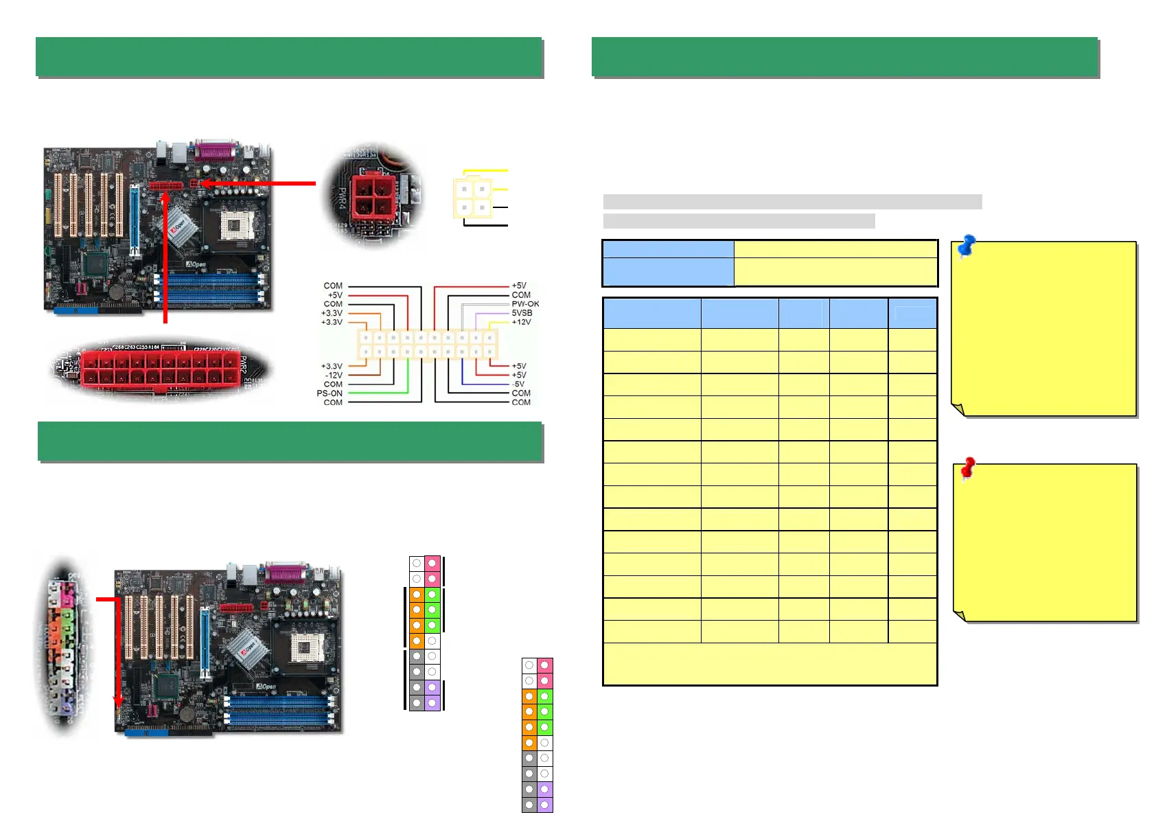
This motherboard comes with a 20-pin and 4-pin ATX power connector as shown below.
Make sure you plug in the right direction. We strongly recommend you to insert the 4-pin
connector before connecting the 20-pin connector.
5. Setting CPU Voltage & Frequency
4. Connecting Front Panel Cable
3. Connecting ATX Power Connector
Full-range Adjustable CPU Core Voltage
This motherboard supports CPU VID function. The CPU core voltage will be automatically
detected and the range is from 0.8375V to 1.6000V. It is not necessary to set CPU Core
Voltage.
Setting CPU Frequency
This motherboard is CPU jumper-less design, you can set CPU frequency through the
BIOS setup, and no jumpers or switches are needed.
BIOS Setup > Frequency / Voltage Control > CPU Bus Frequency
Core Frequency = CPU FSB Clock * CPU Ratio
CPU Ratio 8x, 10x… 24x, 25x, 26x, 27x, 28x
CPU FSB
(Adjustment manually)
FSB = 100MHz-400MHz by 1MHz Stepping
CPU Overclocking
Northwood
CPU
CPU Core
Frequency
FSB
Clock
System
Bus
Ratio
Pentium 4 1.8G 1800MHz 100MHz 400MHz 18x
Pentium 4 2.0G 2000MHz 100MHz 400MHz 20x
Pentium 4 2.2G 2200MHz 100MHz 400MHz 22x
Pentium 4 2.2G 2200MHz 133MHz 533MHz 16x
Pentium 4 2.26G 2260MHz 133MHz 533MHz 17x
Pentium 4 2.4G 2400MHz 100MHz 400MHz 24x
Pentium 4 2.4G 2400MHz 133MHz 533MHz 18x
Pentium 4 2.53G 2530MHz 133MHz 533MHz 19x
Pentium 4 2.6G 2600MHz 200MHz 800MHz 13x
Pentium 4 2.66G 2660MHz 133MHz 533MHz 20x
Pentium 4 2.8G 2800MHz 133MHz 533MHz 21x
Pentium 4 2.8G 2800MHz 200MHz 800MHz 14x
Pentium 4 3.06G 3066MHz 133MHz 533MHz 23x
Pentium 4 3.20G 3200MHz 200MHz 800MHz 16x
Note: With CPU speed changing rapidly, there might be fastest CPU on
the market by the time you received this installation guide. This table is
kindly for your references only.
Attach the power LED, speaker, and reset switch connectors to the corresponding pins. If
you enable “Suspend Mode” item in BIOS Setup, the ACPI & Power LED will keep flashing
while the system is in suspend mode.
Locate the power switch cable from your ATX housing. It is 2-pin female connector from the
housing front panel. Plug this connector to the soft-power switch connector marked SPWR.
Note: Intel 865G/PE and
848P chipset only support
Northwood processor.
Northwood processor
would detect the clock
ratio automatically; you
may not be able to adjust
the clock ratio in BIOS
manually.
Warning: Intel 865G/PE
and 848P chipset support
maximum 800MHz
(200MHz*4) system bus
and 66MHz AGP clock;
higher clock setting may
cause serious system
damage.
+12V
+12V
Ground
Ground
1
SPEAKER
IDE LED
Power Switch
ACPI & Power LED
RESET
SPWR
GND
ACPILED-
GND
ACPILED+
NC
NC
GND
RESET
GND
NC
NC
+5V
IDE LED
IDE LED
+5V
+5V
GND
NC
SPEAKER
1
 Loading...