Safety instructions
Save all warnings and instructions for future reference.
1)
a)
b)
c)
2)
a)
b)
c)
d)
e)
3)
a)
b)
c)
d)
e)
f)
g)
4)
a)
b)
c)
d)
e)
f)
g)
5)
a)
Safety instructions for all operations
Safety warnings common for grinding, sanding, wire brushing, polishing, carving or abrasive
cutting-off operations:
a)
b)
c)
d)
e)
f)
g)
h)
i)
j)
k)
l)
m)
n)
o)
p)
q)
r)
s)
Further safety instructions for all operations
Kickback and related warnings
Kickback is a sudden reaction to a pinched or snagged rotating wheel, sanding band, brush or any other
accessory. Pinching or snagging causes rapid stalling of the rotating accessory which in turn causes the
uncontrolled power tool to be forced in the direction opposite of the accessory’s rotation.
For example, if an abrasive wheel is snagged or pinched by the workpiece, the edge of the wheel that
is entering into the pinch point can dig into the surface of the material causing the wheel to climb out or
kick out. The wheel may either jump toward or away from the operator, depending on the direction of the
wheel’s movement at the point of pinching. Abrasive wheels may also break under these conditions.
Kickback is the result of power tool misuse and/or incorrect operating procedures or conditions and can
be avoided by taking proper precautions as given below.
a)
b)
c)
d)
e)
Additional safety instructions for grinding and cutting-off operations
Safety warnings specific for grinding and abrasive cutting-off operations:
a)
b)
c)
d)
e)
f)
g)
h)
Additional safety instructions for wire brushing operations
Safety warnings specific for wire brushing operations:
a)
b)
c)
Battery tool use and care
a)
b)
c)
d)
Service
Have your power tool serviced by a qualified repair person using only identical replacement parts. This
will ensure that the safety of the power tool is maintained.
For the charger
Intended use
Charge only rechargeable battery packs. Other types of batteries may burst to cause personal injury and
damage.
a)
b)
c)
d)
e)
Electrical safety
When using electric machines always observe the safety regulations applicable in your country to
reduce the risk of fire, electric shock and personal injury. Read the following safety instructions and also
the enclosed safety instructions.
TECHNICAL SPECIFICATIONS
Know Your Rotary Tool
Before attempting to use any tool, familiarize yourself with all operating features and safety require-
ments.(See Figure 1)
Charging Tool
NOTE! The Mini Grinder does not come completely charged from the factory. Be sure to charge tool
prior to initial use.
Turn the hook to ensure that the charger plug can be inserted into the machine charging socket. Insert
the power adapter plug into your standard power outlet.
The blue LED lights located on the top side of the tool housing will start scrolling rear/front to signal the
battery is receiving a charge. Charging will automatically stop when the tool is fully charged. When all
the blue LED lights are always on charging is complete.
Battery Charge Indicator
This tool is equipped with a charge indicator that tells you how much charge your battery has.
When four blue lights are always on, the battery is full. As the battery capacity decreases, the blue light
goes out one by one. When the battery is depleted, the tool will turn off automatically. The blue light will
all go out.
Operating Instructions
Using the Rotary Tool
The first step in learning to use the Rotary Tool is to get the “feel” of it. Hold it in your hand and feel its
weight and balance. Feel the taper of the housing. Always hold the tool away from your face. Accesso-
ries can be damaged during handling, and can fly apart as they come up to speed. This is not common,
but it does happen. Whenever you hold the tool, be careful not to cover the air vents with your hand. This
blocks the airflow and causes the motor to overheat. For best control in close work, grip the Rotary Tool
like a pencil between your thumb and forefinger. (See Figure 2)
The “Golf Grip” method of holding the tool can be used for more aggressive operations such as grinding
a flat surface or using cutoff wheels. (See Figure 3)
Practice on scrap materials first to see how the Rotary Tool's high-speed action performs. Keep in mind
that the work is done by the speed of the tool and by the accessory in the collet. You should not lean on
or push the tool during use. Instead, lower the spinning accessory lightly to the work and allow it to touch
the point at which you want cutting (or sanding or etching, etc.) to begin. Concentrate on guiding the tool
over the work using very little pressure from your hand. Allow the accessory to do the work. Usually, it
is best to make a series of passes with the tool rather than attempt to do all the work in one pass. To
make a cut, for example, pass the tool back and forth over the work, much as you would a small
paintbrush. Cut a little material on each pass until you reach the desired depth. For most work, the
gentle touch is best. With it, you have the best control, are less likely to make errors, and will get the
most efficient work out of the accessory.
Operating Speeds
To select the right speed for each job, use a practice piece of material.
SLIDE "ON/OFF" SWITCH
The tool is switched "ON" by the slide switch located on the top side of the motor housing.
TO TURN THE TOOL "ON", slide the switch button forward. The tool will start working at a speed of
20,000 rpm
TO TURN THE TOOL "OFF", slide the switch button backward. If for some reasons the on/off switch
doesn't work there is always the option to alternatively turn off the tool by the following methods:
Press the minus (–) orange speed control button to bring the speed of the tool to the lowest speed level
(5,000 RPM).
Hold the minus (–) orange speed control button for 5 seconds.Then the tool will be turned off.
SPEED CONTROL BUTTONS
The tool is equipped with speed control buttons. The speed may be adjusted during operation by
pressing on the plus (+) or (-) minus orange buttons located on the top side of the battery housing.
Speed will increment or decrement from a minimum of 5,000 to a maximum of 30,000 rpm. The LED
lights located alongside the blue buttons will illuminate according to the chosen speed. Every time when
the tool is turned off the speed setup goes back to the medium level (20,000 rpm) so it might be neces-
sary to increase/decrease the speed to the level that it was being used.(See Figure 4)
The speed of Rotary Tool is controlled by setting the blue speed control buttons.
Needs for Slower Speeds
Certain materials, however, (some plastics and precious metals, for example) require a relatively slow
speed because at high speed the friction of the accessory generates heat and may cause damage to
the material.
Slow speeds (15,000 RPM or less) usually are best for polishing operations employing the felt polishing
accessories. They may also be best for working on delicate projects as delicate wood carving and fragile
model parts. All brushing applications require lower speeds to avoid wire discharge from the holder.
Higher speeds are better for carving, cutting, shaping, cutting dadoes or rabbets in wood.
Hardwoods, metals and glass require a high-speed operation, and drilling should also be done at high
speeds.
Many applications and accessories in our line will provide the best performance at full speed, but for
certain materials applications, and accessories, you need slower speeds, which is the reason our
variable speed models are available.
To aid you in determining the optimum operating speed for different materials and different accessories,
we have constructed a series of tables. By referring to these tables, you can discover the recommended
speeds for each type of accessory. Look these tables over and become familiar with them.
Ultimately, the best way to determine the correct speed for work on any material is to practice for a few
minutes on a piece of scrap, even after referring to the chart. You can quickly learn that a slower or
faster speed is more effective just by observing what happens as you make a pass or two at different
speeds. When working with plastic, for example, start at a slow rate of speed and increase the speed
until you observe that the plastic is melting at the point of contact. Then reduce the speed slightly to get
the optimum working speed.
Some rules of thumb in regard to speed:
1.
2.
3.
4.
5.
STALL PROTECTION
This tool has a stall protection feature built into it to protect the motor and battery in the event of a stall.
If you stall the tool for too long, or bind the bit in a workpiece, especially at high speeds, it will automati-
cally turn itself off. Simply take the tool out of the material you were stalled in, turn it off for 3 seconds,
then turn it back on again to continue using it. When the battery becomes close to empty, the tool may
shut down automatically more frequent than normal. If this happens, it is time to recharge the battery.
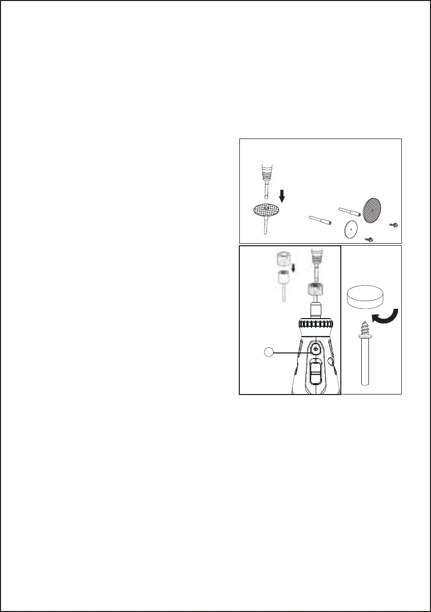
Changing Collets
Using collets is the most precise way to hold an accessory in a high-speed rotary tool. Even at high
speeds and maximum pressure, collets stay tight. ( See Figure 5, Figure 6)
-
-
-
-
-
Installing Accessories
-
-
-
-
Removing Accessories
-
-
Plastic and other materials that melt at low temperatures should be cut at low speeds.
Polishing, buffing and cleaning with any type of bristle brush must be done at speeds not greater than
15,000 RPM to prevent damage to the brush.
Wood should be cut at high speed.
Iron or steel should be cut at high-speed. If a high speed steel cutter starts to chatter — this normally
means it is running too slow.
Aluminum, copper alloys, lead alloys, zinc alloys and tin may be cut at various speeds, depending on
the type of cutting being done. Use paraffin or other suitable lubricants on the cutter to prevent the cut
material from adhering to the cutter teeth.
Press and hold the spindle lock (A), and rotate the shaft with the provided collet wrench (E) until the
shaft lock (A) engages the shaft, preventing further rotation.
With the shaft lock (A) engaged, use the collet wrench (E) to loosen the collet nut (D), if necessary.
Remove the collet nut (D) and old collet (C) using collet Wrench (E), if necessary.
Insert the un-slotted end of the collet (C) in the hole at the end of the tool shaft.
Tighten the collet nut with the collet wrench(E).
Press and hold the spindle lock (A), and rotate the shaft by hand until the spindle lock engages the
shaft, preventing further rotation.
With the spindle lock engaged, use the collet wrench (E) to loosen the collet nut (D), if necessary.
Insert the shank of the accessory into the collet.
With the spindle lock (A) engaged, tighten the collet nut (D) with the provided wrench (E) until the
accessory shank is gripped by the collet. Avoid excess tightening of the collet nut (D).
With the spindle lock (A) engaged, loosen the collet nut (D) with the provided wrench (E).
Remove the accessory.
Using Mandrels
The most common types of the mandrel to use with this tool are the standard mandrel which is used with
cutoff discs, grinding wheels, emery wheels, and cut-off wheels. Screw mandrels are used with polishing
wheels and polishing drums. The drum mandrel is used with sanding drums.
To install:
If using the drum mandrel:
-
-
If using the screw mandrel:
-
-
Balancing Accessories
For precision work, it is important that all accessories be properly balanced. To balance an accessory,
slightly loosen the collet nut and give the accessory or collet a 1/4 in. turn. Retighten collet nut and run
the rotary tool. You should be able to tell by the sound and feel if the accessory is running in balance.
Continue adjusting in this fashion until the best balance is achieved. Replace accessories if they
become damaged or unbalanced.
Shield Rotary Tool Attachment
The rotary shield attachment provides a clear and simple solution for redirecting debris and sparks away
from the user without interfering with the task at hand. The tool shield can be used with right- or left-hand
grip positions and works to deflect debris on a variety of applications, including cutting, sanding, grinding
and polishing. The shield can be quickly adjusted into position, provides easy access to the accessory
without interfering with the workpiece.
Installation Instructions:
Step 1.
Step 2.
-
If using the standard mandrel:
-
-
-
-
-
NOTE: The mandrel washer should be placed between
the mandrel screw and the accessory.
-
Fig.7
Install the mandrel.
Press and hold the spindle lock (A).
Insert the slot end of the provided wrench into the slot
on top of the mandrel and unscrew.
Remove mandrel screw and washer.
Place desired accessory over mandrel shaft and align
the accessory hole with mandrel hole.
Insert mandrel screw with washer through the acces-
sory and mandrel shaft holes.
Tighten using the provided wrench. (See Figure 7)
Align appropriate sized sanding drum over mandrel
and push down to completely cover drum end of
mandrel.
Insert the small end of the provided wrench into the slot
on top of the mandrel and tighten the screw on the
drum mandrel head to expand the drum and securely
hold the sanding drum in place. (See Figure 8)
Align desired accessory hole with mandrel screw head.
Screw accessory into mandrel by twisting clockwise
until secure. (See Figure 9)
Fig.9
Remove the housing cap A from the end of the tool and set housing cap aside. The original
housing cap must be reinstalled when this attachment is not used . (See Figure 10)
Screw the Shield onto the tool using the lock nut B . (See Figure 11)
Step 3.
Using the Shield Rotary Tool Attachment:
Always turn tool power off before adjusting position, changing accessory, and removing attachment.
Rotary Tools cut, sand, grind, and polish in many directions. To accommodate the Rotary Tool’s Maneu-
verability, the Shield can be quickly positioned and repositioned with a turn to the right or left .To extend
the life of the Shield periodically clean with a soft bristle brush or compressed air.
Position the Shield such that it will redirect debris, sparks, and dust away from the user using
the positioning tabs C . (See Figure 12)
Speed Setting for Accessories:
Cleaning, maintenance
Always pull out the mains power plug before starting any cleaning work.
Cleaning
●
●
●
Maintenance
There are no parts inside the equipment which require additional maintenance.
Environmental Protection
- 10 -
Fig.8
A
 Loading...