●To turn engine OFF during a TIMER countdown…
Duringcountdown,
【Hold the knob to the LEFT】
Or,
【Hold the knob to the RIGHT】
ThiswillturntheTIMEROFFtherebyshuttingtheengineOFF.
(Ignitionkeymustberemoved)
●Changing the after idling time during TIMER countdown…
DuringTIMERcountdown,
【Tilt knob UP】
toincreasetime
【Tilt knob DOWN】
todecreasetime.
●To activate Setting Mode…
Whilebatteryvoltageisbeingdisplayed,
【Hold the knob to the RIGHT】
willflashindicatingthatthesetting
modehasbeenactivated
●After setting…
【Hold the knob to the LEFT】
ThiswillreturntotheDisplayMode
When actual battery voltage attains lowerthan set voltage
point,theindicatorstartsflashing.
●To enter the setting mode…
WhiledisplayingO
2
sensorvoltage(mV)
【Hold the knob to the RIGHT】
Willflashindicatingsettingmode
●How to set…
TheO
2
sensorvoltageandA/Fwillalternatelydisplay
(O
2
willdisplaylonger)
InputtheO
2
sensorvoltagecorrespondingtothedisplayedA/F
data
TheA/Fsensordatacanbechangedintheprevioussection
●Once setting is complete…
【Hold the knob to the LEFT】
●To enter the setting mode…
WhiledisplayingA/F
【Hold the knob to the RIGHT
Willflashindicatingsettingmode
●How to set…
TheA/FandO
2
sensorvoltagewillalternatelydisplay
(A/Fwilldisplaylonger)
InputtheA/FdatacorrespondingtothedisplayedO
2
sensor
voltage
TheO
2sensordatacanbechangedinthenextsection
●Once setting is complete…
【Hold knob to the LEFT】
●To activate Setting Mode…
WhileAfterIdlingisbeingdisplayed,
【Hold the knob to the RIGHT】
willflashindicatingthatthesetting
modehasbeenactivated
●For Calculation Mode…(Manual or Auto)
AfterIdlingtimescanbeselectedthroughManualorAutomodes.
TotogglebetweenManualorAutomode,
【Hold the knob to the RIGHT】
●After setting…
【Hold the knob to the LEFT】
ThiswillreturntotheDisplayMode
Operation
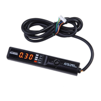
5
PartNamesandFunctions
7SegmentLED LED 4WayKnob
Glossaryofterms:
【Hold】Tiltknobover0.5secinspecifieddirection
【Activate】Tiltknoblessthan0.5secinspecifieddirection
Display Parameters
●
A/F ratio
●
O
2
Sensor Voltage
●
Battery Voltage
●
Countdown time
TurningtheIGkeyONwillactivatethedisplaymode.
(Powermustbeon)
Contentsmaybecheckedthroughflashinglights
Display
To toggle between A/F ratio,O2Sensor Voltage, Battery Voltage,After
Idling Time,
【Activate the knob either UP or DOWN】
ChooseDisplayParameter
Battery Volt-
age
After Idle Time
A/FRatio
O
2
Sensor
Voltage
【Activate the knob either UP or
DOWN】
(V)
(V)
Display Selection
Settheunit
Parameters that can be Set
●
A/F ratio according to O
2
Sensor Voltage
●
O
2
Sensor Voltage according to A/F ratio
●
Minimum Battery Voltage Warning
●
Countdown Time
While in display mode and while the parking brake is activated,
【HoldtheknobtotheRIGHT】ThiswillactivatetheSettingmode
forthatparameter.
TheLEDwillflashtoconfirmsettingmode.
DuringSettingMode【HoldtheknobtotheLEFT】toend.
SettingtheMinimumBatteryVoltageWarning
SettingtheAfterIdlingTime
【Activate the knob either UP or
DOWN】
Set the minimum warning battery
voltage
Choose between10.0V〜15.0Vin
0.1Vincrements
How to Set
If display looks like below,The unit is
in【Auto Mode】
【Tilt the knob either to the
RIGHTorLEFT】toselect
parameters
【Tilt the knob either UP or
DOWN】tochangevalues
【Activate the knobeither UP
orDOWN】toselectAfterIdling
Times
Range: 0 sec 〜 10 min in16
increments
Manual Mode
If display looks like below,The unit is
in【Manual Mode】
“Minute” “Second”
Auto Mode
MAX Countdown
Value
Auto Calculation
Rate
MIN Countdown
Value
This sets the
maximum
amount of
idle time.
Value de-
notes MIN-
UTES. Please
choose
between 1
min〜8 min
This sets the
auto calcula-
tion rate of
the Timer.
There are
three modes,
“H” High
“n” Normal
“L” Low
This sets the
minimum
amount of
idle time.
The vehicle
will always
idle for at
least this
amount of
time.
Choose
between 0~60
seconds in 10
second
increments.
【Hold knob to the RIGHT】
Select Calculation Mode
How to Set
Hold
Select
【Hold knobto the LEFT】toreturn to
DisplayMode
A/Fvalue,O
2
SensorVoltageSetting
ThisproductcontainsvariousA/FandO2Sensorvalues.
ThevaluesrangebetweenA/Fvalue(1)−O
2
sensorvoltage(1)
……A/Fvalue(8)−O
2
sensorvoltage(8)
PleaseusethechartbelowwhenchangingthesettingA/F−O
2
sensorvoltagedata
SettingtheA/FValue
Table1A/Fvalue-O
2
sensorvoltagedatachart
A/F
O
2
SensorV
10.0 12.0 14.0 14.6 15.0 16.0 18.0 20.0
960 900 820 450 100 060 040 020
【Tilting knob to RIGHT or
LEFT】will change the range
of A/F , O2 data (see Table1)
A/FValue
【TiltingknobeitherUPor
DOWN】will allow setting of
desiredA/Fvalue.
O
2
sensorV(1) O
2
sensorV(8)
A/Fvalue(1) A/Fvalue(8)
A/FandO2willalternatelydisplay
(A/Fwilldisplaylonger)
Procedure
O
2
sensorvoltage(mV)
【Tilting knob either UP or
DOWN】will allow setting of
desiredO2value.
【Tilting knob to RIGHT or
LEFT】will change the range
of A/F , O
2 data (see Table1)
A/Fvalue(1) A/Fvalue(8)
O
2
sensorV(1)
O
2
sensorV(8)
O2andA/Fwillalternatelydisplay
(O
2willdisplaylonger)
O
2
SensorVoltageSetting
Procedure
ToturnOFFtheAutoTimer
Turn the TIMER OFF when not in use.
●To turn the TIMER OFF…
Duringdisplaymode,
【Hold the knob to the LEFT】
The7segmentLEDwillread『OFF』shuttingOFFtheunit
●To turn the TIMER back ON…
WhiletheunitisOFF,
【Hold the knob to the LEFT】
Or,
【Hold the knob to the RIGHT】
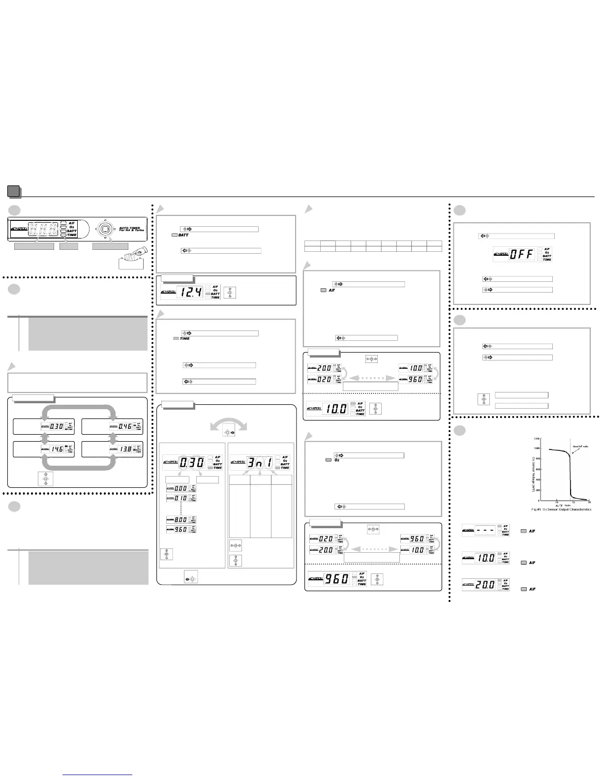
Other…
ThisunitcalculatesatheoreticalA/F
value based upon the factory installed
O
2
sensor.O
2
sensor voltage output
characteristics follow the chart to the
right, where rich conditions produce a
near1Vsignalwhilealeancondition
producesanear 0.1Vsignal. Although
theA/FvalueiscalculatedoffofthisO
2
sensorvoltage,factorssuchasexhaust
temperaturepreventtheO
2
sensorfrom
producing a stable andconstant read-
ing.Pleaseusethisfeatureonlytodeter-
minerichorleanconditions.Also,differ-
ent O
2
sensorswillproducedifferent
voltagereadings.
AbouttheA/Fratiovalues…
If the O2 sensor has not warmed up
enough,
will flash red and green.
Once the O2 sensor warms up, the display
mode will initiate.
When the A/F reaches over 10.0,
will flash red.
When the A/F goes under 20.0
will flash green.
0sec
10sec
20sec
30sec
40sec
50sec
1min
1min30sec
2min
2mi30Sec
3min
4min
5min
6min
8min
10min
This will return to the Display Mode
ThiswillreturntotheDisplayMode
ItreturntotheDisplayMode
 Loading...