Be sure to turn AUTO
LIGHT systems OFF. Fail-
ure to do so may cause the
lights to stay on after the
engine has been shut off.
This may kill the battery.
Be sure to test unit operation
and safety wire operation
after installation.
Never use this unit on a
vehicle that is not intended
for use.
We cannot guarantee proper
operation of this unit on non
application vehicles.
Be sure to secure this unit in
a safe location away from the
driver .
Failure to do so may lead to
accidents.
Do not expose the unit to
excessive shock.
This could lead to unit
malfunction.
Please in tall with our
recommended harness.
If you have any inquiry for
the harness please contact to
your shop.
Always connect the hand
brake wire.
Failure to do so may lead to
accidents.
Be sure to shut off the engine
when sleeping inside the
vehicle
Failure to do so may result in
exhaust poisoning
Never leave the vehicle
while the engine is running
This could lead to accidents
This product is designed for
domestic use only.
It must not be used in any
other country.
Be sure that the unit has
been properly connected
when selling the vehicle.
Also, be sure to provide the
instruction manual to the
new user.
お願い
Remote Door Lock Sys-
tems and Adjustable Steer-
ing Columns may not func-
tion properly after installa-
tion of this unit.
Considerations
●Be sure to check the contents before attempting installation.
●Please notify your dealer of purchase for any missing or broken parts BEFORE
attempting installation.
Parts List
Serial Number…1
Installation Procedures
●Checking the Safety Switch(Parking Brake Switch)
1. Pulltheparkingbrake,start
theengine,andmakesure
theIGkeyisON.
2. SettheTimertoarandom
settingabove30seconds.
3. TurntheIGkeyOFFtoacti-
vatetheTimercountdown.
4. Releasetheparkingbrake
duringthecountdownproc-
ess.
5. Besuretheengineshuts
completelyoff.
Besuretouseapropertoolswhensplicing.
Failuretodosomayleadtofaultyconnections.
Double Sided Tape…1
Securely fasten
with plier
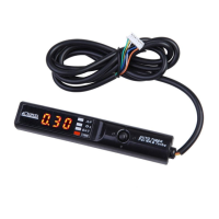
Product Features
2
●Thisunitwillworkonany12V
vehicle.
●O
2
sensorvoltage・A/Fvalue
canbedisplayed.
●DisplaysA/FratioasRICHor
LEANvia2colorsLED
●Displaysbatteryvoltage.Also
warnsofextremelyLOWbattery
voltages。
●16wayadjustmentofCount
downtimingfrom0-10minutes.
●Automaticcountdownfeature.In
ordertoensurethemostoptimum
countdownsettingfromthewid-
estarrayofvehicles,theusercan
choosefrom144differentset-
tings.
●FirstTimertoutilizeO
2
sensor
voltagewhencalculatingcount
downtime.Comparedtotimers
thatonlyusevehiclespeedand
RPM,thisTIMERcansetthemost
accurateafteridlingtimepossible.
●Parking
Brakesafety
switch
3
Control Unit…1
AT3000-0000
RelayandControlUnitInstallation
Please
Thisproductisdesignedtoinstallwithharnesswhichwerecommended.
Itisharnessanyourrecommendedharnesswheninstall.
4
1. Disconnectthenegative
terminalofthebattery.
2. Pulltheharnesscoming
fromthekeycylinder.(In
somevehicles,thewholekey
cylinderisaharness)
3. Inserttheinstallationhar-
nessbetweenthecylinder
andharness.
4. Connectthe3prongTimer
harnesstotherelay.
5. Splicetheblackgroundwire
fromtherelayintotheEn-
gineECUgroundwire.
(Pleaserefertothevehicle
specificwiringdiagram.)
WhennotusingtheO
2
sen-
sor,A/Fratiomonitor,and
automaticafteridlingfunc-
tions,connecttheground
wireconnectortothechas-
sis.
6. Splicethewhitewirefrom
therelay(O
2
sensorsig-
nal)intotheO
2
sensorwire
fromtheECU.(Referto
diagramcharts.)
7. Splicethegrayparking
brakewirefromtherelayto
theparkingbrakeswitch.
(WiththeIGkeyON,be
suretocheckthatthepark-
ingbrakeswitchreads0V
whentheparkingbrakeis
up,and12Vwhenthe
brakeisdown.)
●Installing the Relay
●Mounting the Control Unit
1. Usetheincludeddouble
sidedtapetomount.
2. Mountinalocationthat
doesnotinterferewithdriv-
ing.Connecttorelay.
3. Reconnectbattery.
Do not mount the unit near high temperatures, dust, or under direct
sunlight.
Whenmountingwithdoublesidedtape,takecarenottodamagethe
casewhenrelocating.
Please
Besuretoremovealloilanddebrisfromunitbeforemounting.
Neverpullhardonanyconnectorsorharnesses.
Vehicle Specific Chart…1 Instruction Manual…1
Relay Unit…1
Control Unit…1
Zip Tie…2
Fitting…1
Splice…2
Electro-Tap…1
How to use the Electrotaps (Parking Brake Switch)
Insert wire
Insert wire to be
tapped
■How to Splice the Wire
Thankyouforpurchasingthisproduct..Pleasereadallofthismanualtoen-
sureproperusage.Also,pleasekeepthismanualinasafeplace for future
reference.Besuretoprovidethismanualtothenextuserincaseofownership
change.
Instruction Manual
Instruction Manual
Instruction Manual
■VehiclesthatcannotusetheA/Ffunction
・TitaniumtypeO
2
sensorvehicles
(BNR32SkylineGT−R,(R)PS13Silvia/180SX(ʻ91.1〜ʻ93.10)etc)
■Vehiclesthatcannotutilizetheautoidlingfeature
・VehiclesthatcannotusetheA/Ffunction
・VehiclesthatdonotreadanA/Fnear14.6duringidle
・O
2
sensorsthatwarmupslowly(reads“---”indisplay)
No. PrintDate InstructionManualVer. # Notes
1 8-25-2000 7407-0260-00 1
2 3-10-2004 7407-0260-01 2
3 5-20-2005 7407-0260-02 3
PartName APEXAUTOTIMER
PartCode 405-A011
Purpose EngineAfter-Idlingunit
Application DC12VBodyGroundAutos
Version Information
Never operate this unit
while driving.
Failure to do so may lead to
accidents.
Do not use this product for
any other purpose than the
one listed in this manual.
We are not responsible for
any damages or injuries
incurred from improper
usage of this product.
Discontinue use of this
product immediately if any
unusual odor or smoke
comes from the unit.
Failure to do so may result in
electrical shorts and poten-
tial engine fire.
For safe use of this
product, be sure to read
the Safety Precautions.
Keep the manual in a safe
place after use for future
reference. We have
included these warnings
to protect the user and
dealer from unnecessary
harm. These points have
been marked throughout
this manual by SIGNAL
WORDS. Please refer to
the table on the left for a
glossary of term
meanings.
Safety Precautions
1
This product should ONLY
be installed by a professional
installer.
Installation requires past
experience to prevent dam-
age to the unit and vehicle.
Never disassemble or
tamper with this unit.
This could lead to serious
injury.
Do not leave the engine
running in closed garages or
sealed areas.
Failure to do so may lead to
exhaust fume poisoning.
■GLOSSARY
警告
!
注意
!
Failure to do so may result in
death or severe injury to the
user and others.
Failure to do so may result in
light injury to the user and oth-
ers or product and engine dam-
age.
Failure to do so may result in
product and engine damage.
Display Meanings
PLEASE
WARNING
CAUTION
APEXERA Co.,Ltd. http://www.apexera.co.jp
Head office :1-17-14 Tanashioda,Sagamihara-city Kanagawa,229-1125 JAPAN
ph: +81-42-778-3991 fx+81-42-778-4495
USA office
A’pex Integration,Inc.:330W.Taft Orange,CA.92865,USA
ph : (714)685-5700 fx : (714)685-5701
ELECTRONICS TECHNOLOGY
ELECTRONICS TECHNOLOGY
ELECTRONICS TECHNOLOGY
■Installation Diagram
Controller
Key Swich
Perking Brake Switch
Relay
Vehicle Specific Harnes
(Sold Separately)
Engiine
ECU
O
2
Sensor Signal(White Wire)
Ground(Black wier)
Ground
(Black Wire)
When not using
O
2
Sensor Signal.
(Glay Wire)
R e d:12V+Constant
Blue:IG2Output
Green
:IG1Output