EasyManua.ls Logo

APEXi RSM 405-A912 - User Manual

APEXi RSM 405-A912
52 pages
Print Icon
To Next Page IconTo Next Page
Loading...
Instruction Manual
Product Name
Product Code
Applications
Features
REV / SPEED METER
405-A912 / 405-A916
Only for Vehicles listed in the Wiring
Diagram Booklet
Engine Speed and RPM, Travel Distance
Battery Voltage
0-100,200,400m Acceleration
0-100,200,300km/h Acceleration
Preset 0-250km/h Mid-Range Accel., etc.
REV SPEED METER
Thank you for purchasing this unit. Please
read this manual to ensure proper use of
this product. Also, be sure to keep this
manual in a safe place for future reference.
Be sure to include this instruction manual
when transferring ownership of this product.

Table of Contents

Questions and Answers

  • E
    Elizabeth CrawfordJul 31, 2025
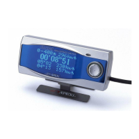
    Why is the speed display incorrect on my APEXi Automobile Accessories unit?
    • C
      Cynthia HerreraAug 1, 2025
      If the speed display on your APEXi Automobile Accessories unit is incorrect, you should first re-check the Speed Pulse Setting and Speed Pulse Adjust Setting. Keep in mind that factory speedometers can have some display error; a difference of over 10km/h at 100km/h is not unusual. Also, if the speed does not display above a certain point, there may be another speed limiter device installed on the vehicle already. If so, remove that device for proper readings.
  • J
    Justin StevensAug 5, 2025
    How to fix incorrect RPM display on APEXi RSM 405-A912 Automobile Accessories?
    • A
      April MurrayAug 5, 2025
      If the RPM display on your APEXi Automobile Accessories unit is incorrect, start by re-checking the Cylinder Setting. Note that there will be a slight difference in readings from RPM difference in the higher RPM ranges. This unit will show correct RPM.
  • M
    Michael NguyenAug 9, 2025
    What to do if acceleration display is incorrect on APEXi Automobile Accessories?
    • K
      Kristen MclaughlinAug 9, 2025
      If the acceleration display on your APEXi Automobile Accessories unit is incorrect, ensure the G Sensor has been calibrated and installed correctly.
  • S
    shellyballAug 13, 2025
    Why is the power measurement incorrect on my APEXi RSM 405-A912 Automobile Accessories unit?
    • R
      Robert BauerAug 13, 2025
      If the power measurement on your APEXi Automobile Accessories unit is incorrect, verify that the vehicle weight has been input correctly. Also, check if the G Sensor has been calibrated and installed correctly, and ensure that Loss Power has been input.
  • Z
    zlevyAug 17, 2025
    What to do if acceleration and power won't display on APEXi Automobile Accessories unit?
    • A
      Antonio WilsonAug 17, 2025
      If the acceleration and power are not displaying on your APEXi Automobile Accessories unit, check if the G Sensor is connected correctly. Note that the G Sensor (sold separately) must be used for these functions.
  • C
    Christopher WilliamsAug 22, 2025
    Why won't the speed limiter cut on my APEXi Automobile Accessories?
    • D
      Dr. Sherry Cunningham PhDAug 22, 2025
      If the speed limiter is not cutting on your APEXi Automobile Accessories unit, verify that the speed limiter has been cut properly. Settings differ according to the vehicle, so re-check the settings.
  • J
    Juan BuckAug 26, 2025
    How to fix APEXi RSM 405-A912 Automobile Accessories when it will not power on?
    • P
      Peter FarrellAug 26, 2025
      If your APEXi Automobile Accessories unit does not power on, check if the battery is connected. Also, ensure that the ECU harness and signal harnesses, as well as the RSM harness and signal harnesses, are connected. Double-check all connectors, splices, and plugs.

Summary

Chapter 1 To Begin

Safety Precautions

Crucial safety guidelines for product use and installation.

Product Features

Overview of the RSM's capabilities and design highlights.

Part Names and Functions

Identifies and explains the functions of all included parts.

About the Optional Parts

Details optional accessories and their benefits for enhanced functionality.

Chapter 2 Initial Settings

Before Using this Product

Essential preliminary steps and checks before operating the unit.

Flow of Initial Setting

Step-by-step guide for the primary initialization process.

About Nissan and HONDA Car Settings

Specific initial setting values for certain Nissan and Honda models.

Tire Size Correction

Adjusting for non-standard tire sizes for accurate speed readings.

Vehicle Weight Input

Inputting vehicle weight for accurate power and loss measurements.

G Sensor Calibration

Calibrating the G sensor for precise acceleration data.

RPM Output

Configuring the unit's RPM output for external devices.

Vehicle Speed Output

Configuring the unit's speed output for external devices.

RPM Warning Display

Setting up visual or audible warnings for Engine RPM.

Vehicle Speed Warning Display

Setting up visual or audible warnings for vehicle speed.

Chapter 3 Operation

Function and Operation

General guide to the unit's functions and how to operate them.

Monitor Mode Overview

Explanation of the Monitor Mode, its display parameters, and modes.

Measure Mode Overview

Overview of the Measure Mode, detailing various measurement functions.

Etc. Mode Settings

Accessing and configuring various system settings and parameters.

Chapter 4 Monitor Mode

Choosing Between 1~4 Channels

Selecting and displaying multiple data parameters simultaneously.

Graph Mode plotting RPM as Horizontal Axis

Displaying data with Engine RPM on the horizontal axis.

Graph Mode plotting Fr;Rr;Lt;Rt Acceleration

Displaying 4-way acceleration data graphically.

Chapter 5 Measure Mode

0-100,200,400 m Acceleration

Measuring acceleration times over specified distances.

0-100,200,300 km;h Acceleration

Measuring acceleration times up to specified speeds.

Preset Mid Range Acceleration

Measuring acceleration over user-defined speed ranges.

Stop Watch (Lap;Split) Measurement

Using the unit as a lap timer or split-time stopwatch.

Power Measurement

Calculating and displaying engine power output.

Loss Power Input;Measure

Measuring and inputting loss power for accurate HP calculations.

Chapter 6 Etc. Mode

Output Setting

Configuring output settings for RPM, speed, and warnings.

Graph Scale Setting

Adjusting the scaling for analog and graph displays.

Vehicle Specific Setting

Setting vehicle-specific parameters for display accuracy.

VFD Adjustment

Adjusting the brightness and display modes of the VFD screen.

G Sensor Calibration

Calibrating the G sensor for accurate acceleration readings.

Initialize All Data

Resetting the unit to factory default settings.

Troubleshooting

Common issues and their solutions for the unit.

APEXi RSM 405-A912 Specifications

General IconGeneral
BrandAPEXi
ModelRSM 405-A912
CategoryAutomobile Accessories
LanguageEnglish

Related product manuals