230
instruction Manual
Aphex Systems Ltd. Model 230Page 6
230
master voice channel
Page 7Aphex Systems Ltd. Model 230
3.0 Installation & Interfacing
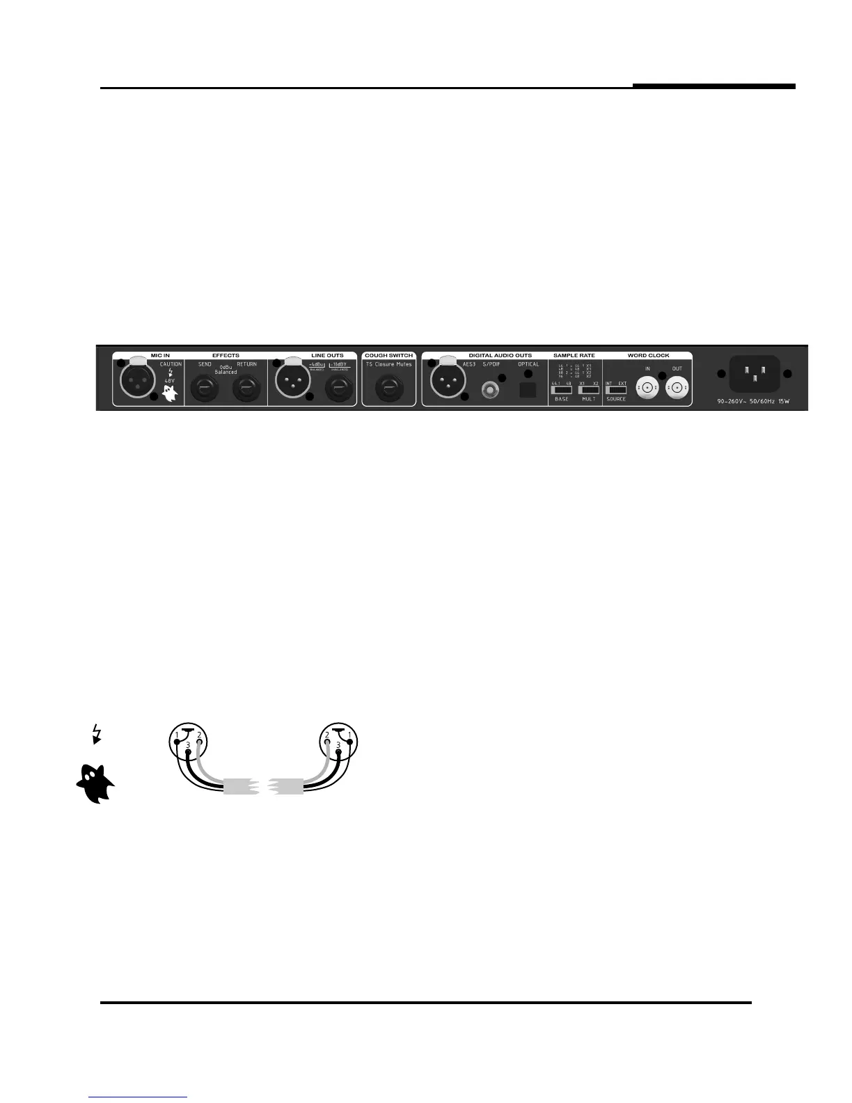
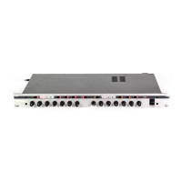
3.4 MIC INPUT CONNECTION
The microphone input connector is located on the
rear panel. It is the standard XLR-3F type. Use only
properly wired balanced mic cables.
CAUTION: Beware that 48 volt PHANTOM POWER
may be applied to the microphone input, creat-
ing a potential shock hazard. Standard practice
dictates shutting off the phantom power before
plugging or unplugging microphones. Wait at
least 10 seconds for the voltage to fall sufficiently.
This is not only for safety, but for protection of
sensitive microphones against power inrush.
3.5 INSERT JACKS
The Model 230 allows you to insert additional signal
processing between the 230’s front-end dynamics
processing and the aft-end equalizer block. Both
Send and Return jacks are balanced and run at
approximately 0dBu. This is a perfect place to insert
an external reverb unit or profanity delay. Other than
that, we can think of no external processing that
would be necessary, but you have the option to put
anything there that you wish as long as it returns a
nominal level.
Direct feed-through occurs with the normalling con-
tacts of the jacks. If you plug into either the SEND
or RETURN jack, the internal path is interrupted. You
need to be sure you have a viable send-return circuit
externally or there will be no audio output from the
230.
There is no insert bypass switch. Once plugged in, the
insert is always inserted. If you can’t get any output
from the 230, make sure the inserted gear is operat-
ing before you assume the 230 is defective.
3.1 INSTALLATION
The Model 230 occupies a single rack space (45mm or 1-3/4 inches) of a standard EIA equipment rack.
When rack mounting, use appropriate cushioned rack screws. Never restrict air flow through the device’s vents.
When installing the units into a rack, distribute the units evenly. Otherwise, hazardous conditions may be cre-
ated by an uneven weight distribution. Connect the unit only to a properly rated supply circuit. Reliable earth-
ing (grounding) of rack mounted equipment should be maintained. Try not to position the 230 directly above
devices that generate excessive heat such as power amplifiers (unless adequately ventilated) or near equipment
with heavy transformer hum fields.
3.2 REAR PANEL VIEW
3.3 AC LINE CONNECTION
Use only a power cord that carries approvals for use in your location. The 230’s internal power supply is
designed to operate from all nominal power sources from 100 to 240 volts a.c. at 50/60Hz without requiring
the user to change any settings. In case of failure, do not attempt to change the internal fuse because it will
never blow unless the power supply fails catasrophically. The power supply will need to be serviced by a com-
petent service technician in such a case.
PROPER MICROPHONE CABLE WIRING
Female XLR Male XLR
AUTIONC
48V