Do you have a question about the Aphex Compellor and is the answer not in the manual?
Dynamic Verification Gate monitors short/long term levels, impedes gain changes, prevents release during pauses.
Dynamic Recovery Computer allows rapid recovery from gain reduction under complex wave conditions, preserving transients.
Freezes gain reduction release when input falls below threshold, eliminating noise swells.
Modulates gain based on input difference, widening stereo image without mono issues.
Optimizes audio input for stations, making them 'jock proof' and cleaner sounding.
Achieves maximum level on tape, fixes mic technique issues, and cleans recordings.
Controls dynamics for live audio, placing mics and vocals, protecting speakers.
Matches levels from multiple sources for film audio, especially optical soundtracks.
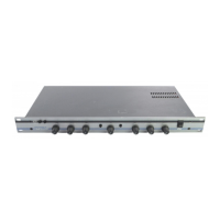
Unit is designed to mount in a standard 19" rack, occupying 1 rack space.
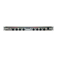
Uses standard XLR connectors, interchangeable for American or European standards.
Details input (50K/25K Ohm) and output (20/10 Ohm) impedances and termination needs.
Allows internal adjustment of nominal operating level for system matching and optimization.
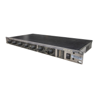
Operates on 90-250 VAC, 50-60Hz, with voltage selection via rear card.
Explains the Compellor's ideal use for dynamic range control without audible artifacts.
Step-by-step guide on setting up and adjusting controls for desired compression and leveling.
Describes the specialized instrumentation amplifier for differential gain and high common mode rejection.
Features the Aphex 1537A Voltage Controlled Attenuator for gain management.
Discusses the refined balanced differential line driver and its unique cross-coupled bridge circuit.
Explains the circuit that catches peaks with a fast attack and a 12dB ceiling above nominal.
Details the concept of leveling using a slow integrator and pulse train for smooth level control.
Covers the DRC module, controlling attack/release characteristics based on user settings.
Explains the DVG circuit's role in providing signals to sidechains and indicating operation.
Describes the circuit that detects silence and freezes gain reduction to prevent noise swell.
Details the feature that adds out-of-phase alternate channel audio to widen the stereo image.
Procedure to verify compression performance using an oscillator and meter readings.
Procedure to test leveling capabilities and tracking with varying oscillator levels.
Procedure to test the peak limiter's response using a special fixture.
Provides sample test data for compression and leveling tests.
Step-by-step guide for safely disassembling the unit for maintenance or repair.
Provides schematics and parts for the input/output and primary processing sections.
Includes schematics and parts for the unit's control interface and display logic.
Details the power supply schematics and component list for the unit.
| Brand | Aphex |
|---|---|
| Model | Compellor |
| Category | Music Equipment |
| Language | English |