Revision 02.A.004/2021.06 9
6. INSTALLATION
6.1. General recommendations
- It is recommended that the flow direction is in the direction of the arrow on the sensor,
the transducer is also factory set to work in this direction. The flow in the opposite direction to
the arrow is shown as a negative value. If it is necessary to mount the sensor upside down,
please contact the manufacturer.
- Before installation, check if there is enough space next to the flange for installing the flow
meter with the use of bolts and nuts.
- During the measurement, the entire space inside the sensor should be filled with the meas-
ured liquid.
- Fix the pipework on both sides of the flowmeter to avoid vibration and sag in the pipework from
affecting the measurement.
- If the flowmeter is installed in a pipeline with a larger ID, use a reducer that ensures axial fixa-
tion without increasing stress on the sensor pipes and flanges. Remember to keep straight
sections in front of and behind the sensor.
- During installation the straight sections should be of nominal diameter of the sensor (DN) with
lengths of at least 5DN before and 3DN after the sensor.
- When installing the sensor on an insulated pipe (e.g. glass, plastics etc.) please insulate
the system with earthing rings connected with ground terminal of the sensor ➔ Figure 11.
- Conductive connection between ground (enclosure) of the sensor and liquid is necessary
for correct measurements.
- During assembly it is essential to install a seal between the flanges of the sensor and the
piping. When using grounding rings, seal use rings on both sides.
- Do not use gaskets made of hard materials as they may damage the Teflon lining or, in the
case of rubber lining, fail to ensure a sufficient tightness of the installation.
- Make sure that no sealing element enters the lumen of the pipeline as this may introduce
turbulence into the flow and disrupt the operation of the flowmeter.
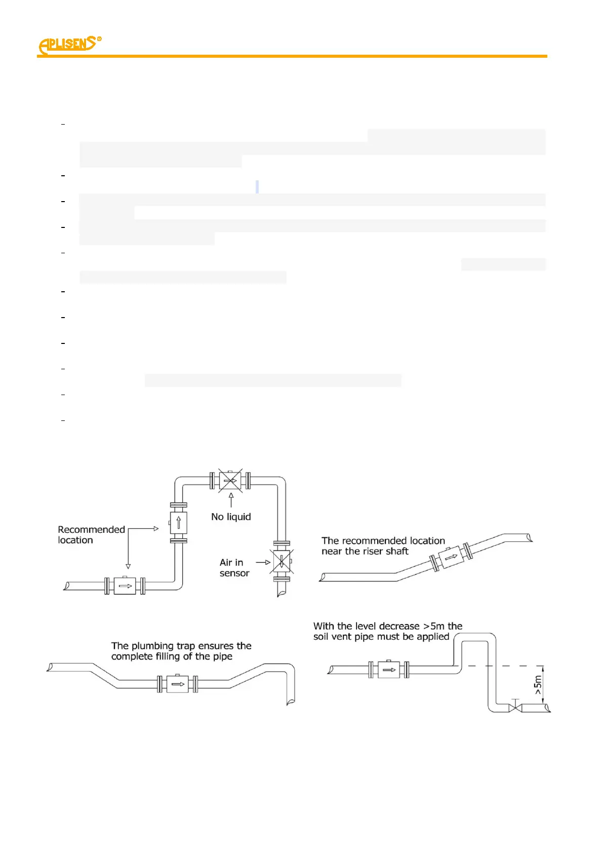
6.2. Recommended installation methods for flow sensor
Figure 1. Recommended examples of sensor installation.
 Loading...