Flush upstream piping thoroughly to remove any foreign matter prior to installing the device.
Do not install the unit in areas subject to freezing temperatures.
INSTALL THE DEVICE WITH THE ARROW ON THE VALVE POINTING IN THE DIRECTION OF FLOW.
It is important that this unit be installed between shut-off valves in order to isolate the unit during repair and
service.
Provide sufficient support on the piping system upon installation of this unit.
Increasing the spring load through the adjusting screw will increase
Under flow conditions, the pressure under the diaphragm will start to fall below the set pressure causing the
spring and the supply pressure to open the valve and allowing more water to flow.
The amount of water that will pass through the valve depends on the difference between the inlet and the outlet
pressure. As the pressure differential increases, the volume of water increases.
MAINTENANCE
Regular inspection, testing and cleaning of water pressure reducing valve and other components in a piping sys-
tem assures maximum life and proper function.
NOTE: PRIOR TO DISASSEMBLING THE UNIT, SHUT-OFF WATER SERVICE AND RELIEVE PRESSURE DOWN-
STREAM.
a) DISASSEMBLY OF SEAT
1. Unscrew bottom plug.
2. Unscrew seat disc holder.
3. Remove seat.
b) DISASSEMBLY OF SEAT DISC
1. Remove bottom plug and seat disc holder.
2. In the seat disc holder, remove seat disc by
unscrewing the seat screw.
c) DISASSEMBLY OF DIAPHRAGM
CAUTION:
CAP IS SPRING LOADED.
d) DISASSEMBLY OF BY-PASS ASSEMBLY
Body
Seat O-Ring
Seat
Seat Screw
Seat Disc Washer
Seat Disc
Seat Disc Holder
Nameplate
Lock Nut
Cap Bolt
Cap
Spring
Diaphragm
Yoke
TROUBLE-SHOOTING
PROBLEM POSSIBLE CAUSE
SOLUTION
INSTALLATION
OPERATION
3. Excessive noise within the pipe-
line at the PRH.
(c) Damaged or cut diaphragm
(d) By-pass leaking
-Inspect and replace if defective.
-Inspect and replace if defective.
-Replace
1. Inlet pressure equalizes outlet
pressure at no flow conditions.
(a) Seat disc not sealing tight
against seat
2. Outlet pressure rises above inlet
pressure.
By-pass assembly not opening or
clogged
Thermal expansion downstream
High water velocity at the pipeline
can sometimes cause a whistling
noise or hum.
DIMENSIONS (in.) & WEIGHTS (lbs.)
Size
(NPT)
A BCD
EF
1/2" 4-1/8 2-1/4 7 1-7/8 8-3/8 4 7 6
3/4" 4-1/8 2-1/4 7 2-7/16 9 4 7 6
8124-11/1610-1/447-1/22-5/164-1/8
EXAMPLE:
NOTES:
1) Repair kits contact factory
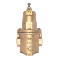
MODEL PRH
High Capacity
Water Pressure Reducing Valve
I-5957-00
RELIEVE SPRING PRESSURE BY
UNSCREWING THE ADJUSTING SCREW
BEFORE ATTEMPTING TO REMOVE CAP!
1. Remove cap bolts.
2. Remove cap, spring retainer, and spring.
3. Unscrew diaphragm nut.
4. Remove diaphragm washer and diaphragm.
1. Unscrew bottom plug and remove seat disc holder.
2. Relieve spring pressure on the cap and remove
cap bolts. Dismantle the spring retainer and spring.
3. Remove yoke with diaphragm attached.
Do not unscrew diaphragm nut.
4. Unscrew the by-pass assembly.
By-Pass Assembly
Bottom Plug
Bottom Plug O-Ring
Adjusting Screw
Self Sealing Washer
Spring Retainer
Diaphram Nut
Diaphragm Washer
(b) Seat O-ring may be cut or damaged
Leakage within the valve may be due
to the following:
1"
242912-1/23-3/166-3/4
232913-1/83-3/166-3/4
384712-1/23-1/28-1/82"
374912-1/23-1/28-1/8
708720-1/215-1/810-3/83"
497912-1/23-1/210-3/82"
5512-1/23-1/210-3/8
9224-1/215-1/812-1/23"
1-1/4"
1-1/2"
2-1/2"
Flanged
2-1/2"
3-15/16
10
10
3-3/8
3-7/8
4-5/8
5-15/16
6-15/16
16
16-11/16
6-1/2
6-1/2
7-5/8
7-5/8
9-3/4
105
1363-15/16
6-1/4
7-1/8
8-1/8
20
21-11/16
7-5/8
7-5/8
9-3/4
W/STRAINER W/OUT STRAINER
WGT. WGT.
At static (no flow) conditions, inlet
FLOW CURVES
Flow curves are based on static conditions of: Inlet pressure = 100 psig.
Outlet pressure = 50 psig
E (REF.)
A
F
500 100 150 200 250 300 350 450400
0
5
10
15
25
20
½"
¾
"
1" 1½" 2" 2½" 3"
PRESSURE FALL-OFF (PSI)
FLOWRATE (GPM)
the set pressure. By decreasing the spring load (turning the adjusting screw counterclockwise), the set
pressure decreases.
The APOLLO PRH must be installed in a conveniently accessible location to facilitate
testing, repair and maintenance.
The PRH is designed to reduce high supply pressure (up to 400 psig) to a lower outlet pressure within
it's adjustment range. The standard unit is factory set at 50 psig outlet pressure (static condition), and is ad-
justable from 25 to 75 psig (low and high pressure setting option available).
The PRH is designed so that it can be serviced through the bottom plug without removing the cap and
disturbing the pressure setting. Both the seat and seat disc assembly can be accessed through the bottom plug.
pressure of 100 psig and outlet set pressure of 50 psig
(standard), a PRH-3/4" unit will deliver 23 gpm
of water with a 10 psi fall-off (40 psi reduced flow
pressure). If outlet set pressure at static condition is
less than 50 psig, deduct 20% from capacity shown.
(36H SERIES)
-Slight adjustment on the PRH may
eliminate the noise. If not, the line or the
PRH may be too small for the application.
1-1/4"
WARNING! This product contains chemicals known to the State of California to cause cancer and birth defects or other reproductive harm.
(California law requires that this warning be given to the consumers in the State of California.)
THIS PRODUCT MEETS THE REQUIREMENTS OF THE EPA SAFE DRINKING WATER ACT.
(C)
B
D
During static (no-flow) conditions, the valve is closed because the magnitude of the diaphragm force exposed to
the downstream pressure is greater than the valve spring force. The balance of the forces on the supply and
spring pressure (which tends to open the valve) against the diaphragm pressure, determines the outlet or re-
duced pressure downstream of the valve.
PAGELAND, SC 29728
1418 S.PEARL ST.
CONBRACO INDUSTRIES INC.
TELEPHONE (704)841-6000
www.apollovalves.com
-Inspect by-pass washer and rubber
ball.Rubber ball should move freely inside
the housing. If defective replace the
by-pass assembly.
For more information visit www.apollovalves.com.
-Disassemble the unit, clean and replace
the by-pass assembly, if defective.
-Rubber ball should move freely inside the
housing.
Disc Holder O-Ring
On units with strainer option, it is recommended to remove and clean the strainer screen periodically as service
conditions warrant, to prevent malfunction.