2
APD0602 A140513 Wireless CO Install
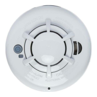
The Wireless Carbon Monoxide Alarm contains a sounder which generates
the ANSI S3.41 temporal 4 pattern in an alarm condition (see Table 1 for
temporal 4 pattern). In alarm, a message is also sent to the control panel
and the detector’s ID is displayed at the console. During an alarm condition,
pressing the detector’s hush button will silence the sounder for ve minutes.
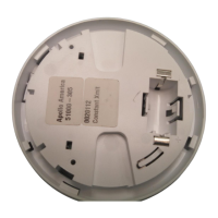
The mounting base installation is simplied by the incorporation of features
compatible for both drywall fasteners (not supplied) and other methods.
Tricolored LED (green, yellow, red) and a sounder on the detector provide
local visual and audible indication of the detector’s status as listed in Table 1.
During initial power-up the LED blinks alternately green, yellow then red. It
takes about 60 seconds for the detector’s CO sensor to stabilize.
After power-up has completed and the detector is functioning normally, the
green LED blinks once every 12 seconds.
Status LEDs
Sounder
(does not pulse
the sounder and
LED concurrently)
Radio
signalling
Normal
Green ash every
12 seconds
Off
Normal
(None)
Alarm/ Test
Red ash every
12 seconds
ANSI S3.41
temporal 4 (press
button to hush
for 5 minutes)
Alarm
Detector
trouble
Yellow ash
every 6 seconds
One 100ms chirp
every 45 seconds
Fault
Low battery
Yellow ash
every 12 seconds
One 100ms chirp
every 45 seconds
(press button
to hush for 12
hours)
Low Battery
Detector end
of life
Yellow ash
every 23 seconds
One 100ms chirp
every 45 seconds
Fault
Powerup
Green, yellow,
red ash
sequence every
12 seconds
One 100ms chirp
at end of power-
up sequence
None
Tamper
Green, yellow,
red ash
sequence every
12 seconds
Off Tamper
Table 1. Detector status and indication