4 5
Sensitivity setting
The sensitivity switch is available and is used to set the sensitivity of the fl ame detector to
class 1 or class 3. For most practical purposes the switch should be set to class 1 (default
setting), the sensitivity required to detect fl ames as described in the section ‘Quantities
required and positioning of detectors’, page 3.
In exceptional cases the fl ame detector may be set to class 3 operation in order to avoid
nuisance alarms being caused by radiation sources that are close to the detector and can
not be moved. The rotary sensitivity switch is located on the detector rear behind the label.
To set to class 3, rotate the switch 90° clockwise. To return the sensitivity switch to the class 1
setting, rotate the switch 90° counter clockwise.
Installation
The fl ame detector is mounted on any Series 65 base and would normally be wall or ceiling
mounted preferably on an adjustable bracket to adjust the angle of view.
The standard base mounting is used for horizontal viewing, eg, along corridors or along the
length of industrial processes or vertical viewing inside fume cupboards or over hoppers.
Flame detectors should be fi tted to solid walls or rigid constructions that do not move and
are not subject to vibration.
If fi tting to an XP95 Zone Monitor do not fi t more than one device per zone.
If fi tting to a conventional control panel, please verify the quantity per zone with the
chosen panel manufacturer.
Wiring
The fl ame detector has fi ve connections: L1 IN, L1 OUT, L2, -Remote and functional earth/
screen. The connections are accessed by removing the detector from its base. See Fig 4 for
connection diagram.
To meet the requirements of EN54-10 clause 5.4, where the ratio of the response points
Dmax:Dmin should not exceed 1.41. The horizontal and vertical viewing angles α
max
should
not exceed ± 40°.
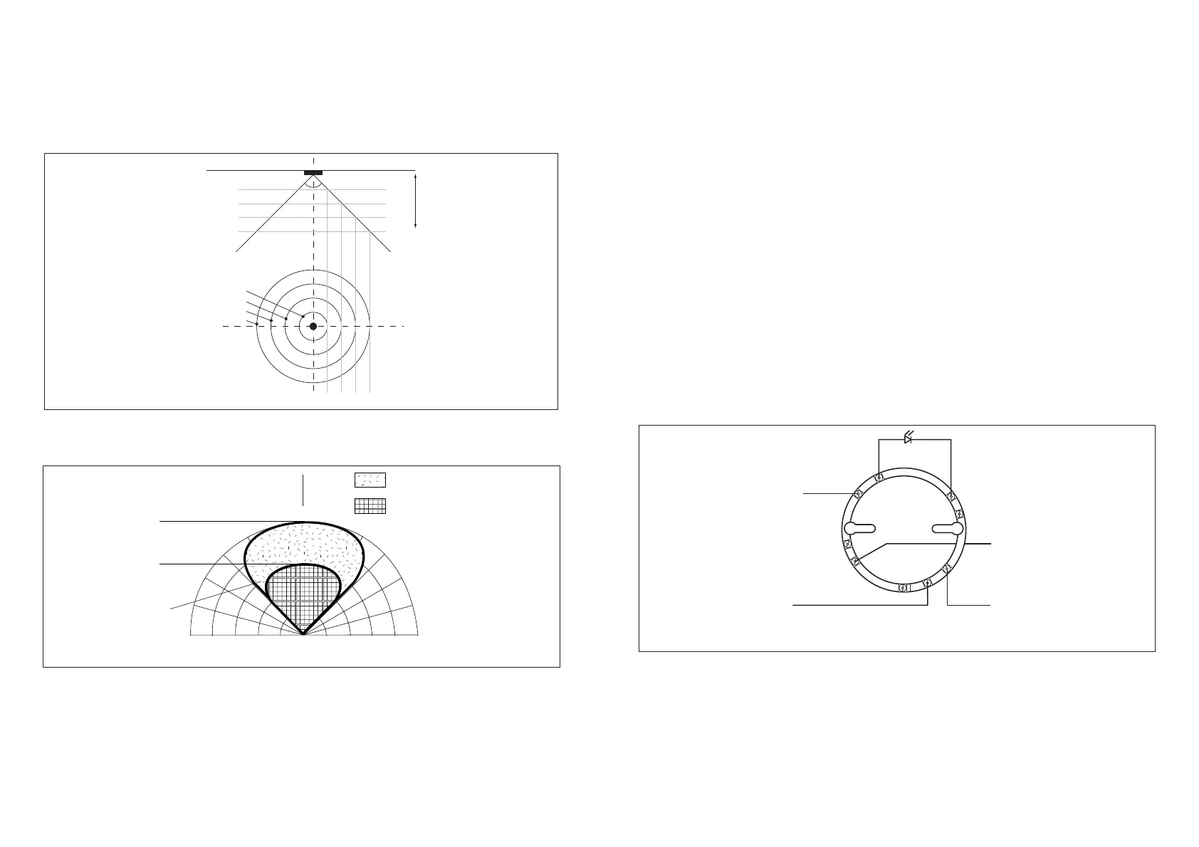
The Marine UV Flame Detector has an angle of view of approximately 90°, as shown in the
diagram below.
Fig 3 Angle of view of Marine UV Flame Detector
n
n
n
n
n
n
MÁFLAMESEEN
ATMINSTRAIGHTLINE
ROMFLAMEDETECTOR
MÁFLAMESEEN
ATMINSTRAIGHTLINE
ROMFLAMEDETECTOR
MÁFLAMENOTSEEN
ATMSINCEITISNOT
INTHEFIELDOFVIEWOF
HEFLAMEDETECTOR
M M
CENTRELINEOFDETECTOR
DETECTIONOFMÁFLAME
DETECTIONOFMÁFLAME
© Apollo Fire Detectors Limited 2000-2005/RHD
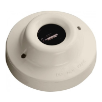
The Marine UV Flame Detector can also be ceiling mounted, positioned above the antici-
pated fl ame source or at the centre of the area to be protected, perpendicular to the
fl oor below. If the detector cannot see the whole of the area to be protected, one or more
additional detectors may be required. Refer to the angle of view diagram Fig. 3 to establish
the detector performance. The area of detection is dependent on the detectors height
above the likely source of fl ame. The detector has a 90° conical fi eld of view or 45° either
side of the viewing axis centre line. The maximum ceiling height is 20m. If the detector is
perpendicular to fl oor and at a height of 10m then the detector will view a circular fl oor
area below with a 10m radius (20m diameter circle).
Vertical Plane
Ceiling
5m
10m
15m
20m
Floor
Plan View
10m Dia.
20m Dia.
30m Dia.
40m Dia.
Height
© Apollo Fire Detectors Limited 2009/TP
Fig 2 Ceiling mounting example
Fig 4 Marine UV Flame Detector base connections
+
From control panel To next device
L2
L1 OUT
R–
EARTH
–
L1 IN
© Apollo Fire Detectors Limited 1997-2011/RHD/TB/EKC
Terminal Descriptions
1 L1 IN +Line IN
2 L1 OUT +Line OUT
3 L2 – Line IN and OUT
4 –R –Remote LED
5 EARTH Functional Earth/Screen (Isolated)
www.acornfiresecurity.com
www.acornfiresecurity.com
 Loading...