6 3
Functional Testing
Testing the operation of the detector can be achieved in two ways, provided it is safe to do
so:
• A real fl ame from a portable fl ickering yellow bunsen fl ame or cigarette lighter
• A portable fl ame detector tester unit.
Maintenance Guide
The fl ame detector is designed to give years of trouble-free operation with minimal atten-
tion. However the periodic maintenance steps listed below are essential to maintain reli-
able fi re protection.
1. Inform all appropriate personnel of intention to work on the fl ame detector.
2. Disable any automatic systems that may be activated by the fl ame detector if not
required as part of the maintenance check.
Alarms Extinguishers Control
Audio/Visual Gas systems Plant stops
Auto dialers Water sprays Dampers/doors
3. Check that the fl ame detector’s control panel is functioning correctly and shows no
faults.
4. Inspect the detector viewing window for any build-up of dust or other contaminants
on the optical surface. If necessary clean the optical surface with a cotton wipe wet
with commercial liquid glass cleaner, but not polishes. Rinse with clean water and dry
with a clean cloth.
The detector specifi cation for performance is with a clean optical sensor window.
Contaminants like dust, oil and paint will reduce sensitivity.
5. Ensure the detector still has a clear line of sight of the area it is protecting and no
obstacles obstruct its view.
6. Check that the detector is securely fi tted.
7. Visually check the exterior of the detector for any mechanical or corrosive damage.
8. Test the operation of the detector with either a portable fl ame sensor test unit or if
practical a fl ame.
9. Reinstate any automatic system disabled during maintenance.
Quantities required and positioning of detectors
The number of detectors required and their positioning depends on:
• the anticipated size of the fl ame
• the distance of the fl ame from the detector and
• the angle of view of the fl ame detector
The fl ame detector is designed to operate to Class 1 performance as defi ned in EN54-10.
The detector will, therefore, detect a fl ame of approximately 0.1m² or a clear fl ame of
0.25m² at 25m.
In fact, the fl ame detector will detect fi res at distances of up to 40m, but the fl ame size at
such distances needs to be proportionally greater in order to be sure of reliable detection.
Thus the fl ame that can be detected at 25m, provided that its size is not less than 0.1m², will
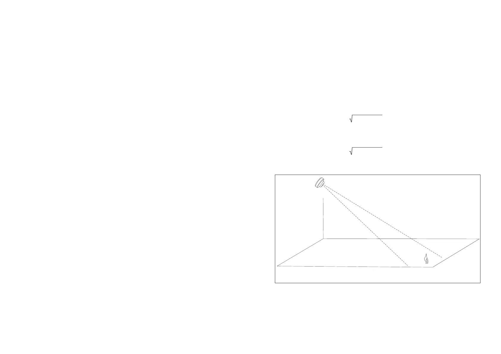
have to be 0.4m² in order to be detected at 40m. In a rectangular room the distance from
the fl ame detector to the fi re is calculated by the formula:
L² + W² + H²
In the example shown in Fig 1 the room in which the fl ame detector is to be installed meas-
ures 20m x 10m x 5m; the distance from the detector to the fl ame will therefore be:
20² + 10² + 5²
Height
Width
Length
© A
ollo Fire Detectors Limited 2000-2010/RHD/TB
Fig 1 Calculation of distance from detector to fl ame
The fl ame detector should be positioned at the perimeter of the room, pointing directly
at the area of the anticipated fl ame or at the centre of the area to be protected. If the
detector cannot ‘see’ the whole of the area to be protected, one or more additional
detectors may be required.
The fl ame detector is not affected by most normal indoor light sources but should be posi-
tioned so that daylight is not in view.
www.acornfiresecurity.com
www.acornfiresecurity.com
 Loading...