Apollo 8 Hardware Manual Interconnections 35
Apollo Expanded: Multi-Unit Wiring
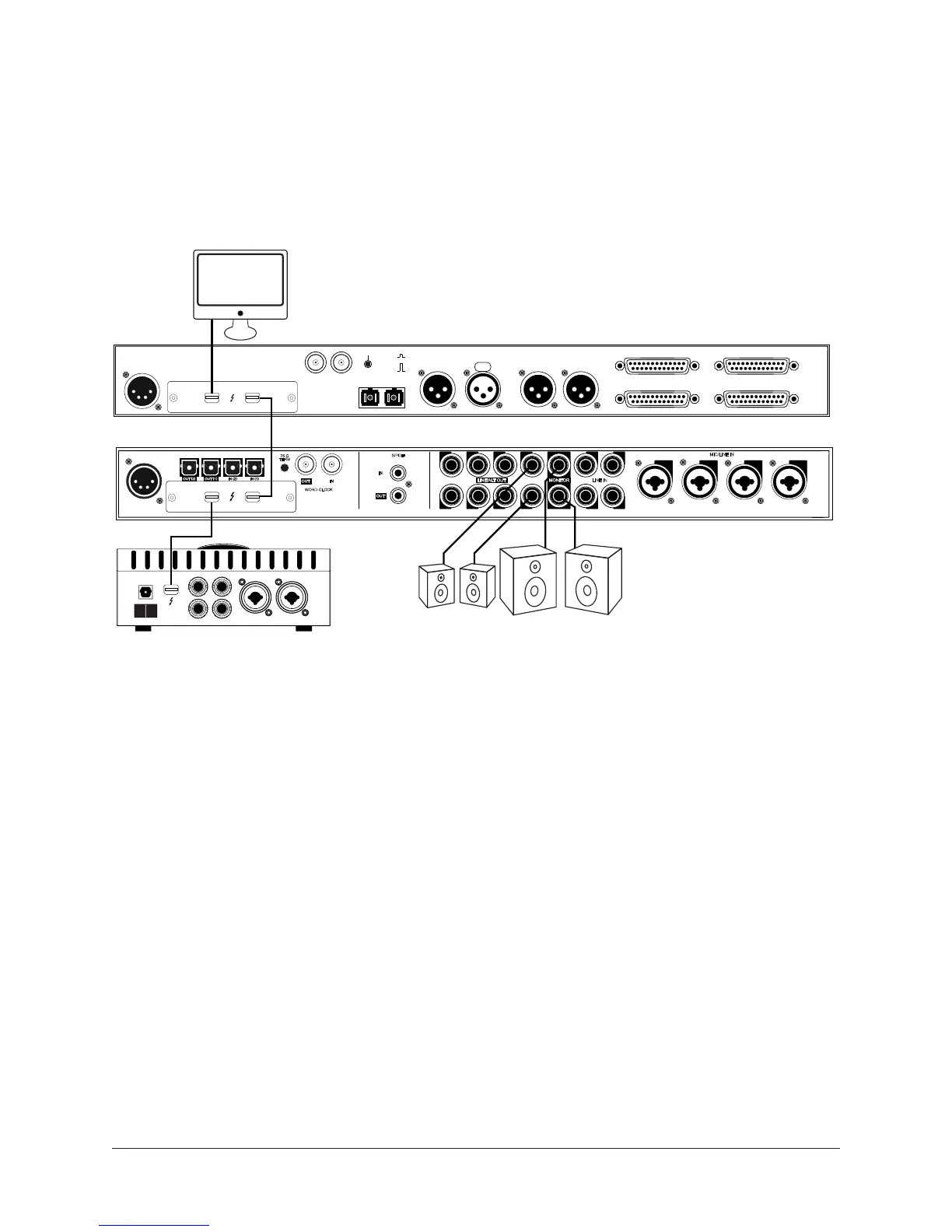
The diagram below illustrates how to interconnect multiple Apollo units and the host computer
via Thunderbolt.
Important: For complete details about system operation when multi-unit cascading, see
the Apollo Software Manual.
Cables Required
• One Thunderbolt cable for each Apollo unit
Note: All Apollo rack units require Thunderbolt connections (FireWire cannot be used).
Apollo Expanded Wiring Notes
• A single Thunderbolt cable is required for all Apollo unit interconnections. Connect one
Thunderbolt cable to the host computer and one Thunderbolt cable between Apollo units.
• Thunderbolt 1 or 2 ports may be mixed and used for any/all connections.
• The computer and all Apollo units must be connected to the same Thunderbolt bus.
• Apollo device ordering and Thunderbolt ports used (second port on Apollo vs. second port
on computer, placement within daisy chain, etc) is not important.
• In this wiring example diagram, the Apollo 8 in the center is the designated monitor
(master) unit. Connect speakers (including ALT speakers) and any cue outputs to the
monitor unit only.
• Do not connect more than one Thunderbolt cable between the same two devices (the
Thunderbolt protocol is bidirectional).
• Do not interconnect any Word Clock, FireWire, ADAT, or MADI ports between any Apollo
units.
1
WORD
CLOCK
4 2
MIC/LINE IN
3 1
LINE IN
7 5
ADAT S/MUX
75 Ω
TERM
68R
L1357
248 6
WORD CLOCK
S/PDIF
POWER OUT
ON
OFF
IN
75 OHM TERM
WORD CLOCK
MON OUT (R) 2 MON OUT (L) 1
LINE OUT 1-8 LINE IN 1-8
LINE IN 9-16
MADI OUT MADI IN
AES/EBU OUT AES/EBU IN
PUSH
LINE OUT 9-16
Expander Unit
Monitor Unit
Thunderbolt
Mac
IMPORTANT: Connect speakers
and cue outputs to monitor unit only
Multi-Unit Wiring
Thunderbolt Connections
Expander Unit
Monitor Speakers
ALT Monitor
MIC/LINE 1
MIC/LINE 2
3 L
4 R
LINE OUT MONITOR
OPTICAL IN
OFF ON
POWER