2
In setup mode the volume can be adjusted by holding the magnet adjacent to the ashing setup
LED and removing it at the desired volume level. If min or max volume is reached, the con rmation
LED stops ashing. To alter the direction of adjustment, remove the magnet for one second and re-
apply. Saving the volume setting is performed at the control panel.
Please check with panel manufacturer for compatibility of the above setup/test modes.
Technical Data
Operating voltage 17–28V DC
Switch-on surge 1.5 mA < 10s
Quiescent current (non-polling) 1.4 mA Nominal
Alarm current (non-polling) max
Sounder 9.5 mA
Visual Indicator 8.8 mA
Sounder with Visual Indicator 13.4 mA
Alarm power
Sounder 266 mW
Visual Indicator 246 mW
Sounder with Visual Indicator 375 mW
IP Rating 21C
For sound pressure levels measured to EN54–3 see document PP2203
and for isolator operation information see document PP2090,
both available on request.
3
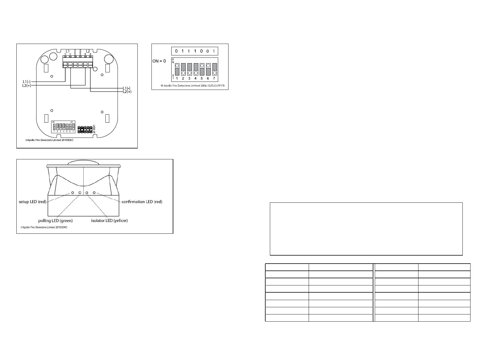
Individual Address Setting
The address of the Open Area Voice Sounder is set using segments 1-7 of the DIL switch.
Each switch is set to “0” (ON) or “1”, using a small screwdriver or similar tool. A complete list
of address settings is shown below.
DIL switch DIL switch DIL switch DIL switch DIL switch
setting setting setting setting setting
addr 1234567 addr 1234567 addr 1234567 addr 1234567 addr 1234567
1 1000000 11 1101000 21 1010100 31 1111100 41 1001010
2 0100000 12 0011000 22 0110100 32 0000010 42 0101010
3 1100000 13 1011000 23 1110100 33 1000010 43 1101010
4 0010000 14 0111000 24 0001100 34 0100010 44 0011010
5 1010000 15 1111000 25 1001100 35 1100010 45 1011010
6 0110000 16 0000100 26 0101100 36 0010010 46 0111010
7 1110000 17 1000100 27 1101100 37 1010010 47 1111010
8 0001000 18 0100100 28 0011100 38 0110010 48 0000110
9 1001000 19 1100100 29 1011100 39 1110010 49 1000110
10 0101000 20 0010100 30 0111100 40 0001010 50 0100110
51 1100110 61 1011110 71 1110001 81 1000101 91 1101101
52 0010110 62 0111110 72 0001001 82 0100101 92 0011101
53 1010110 63 1111110 73 1001001 83 1100101 93 1011101
54 0110110 64 0000001 74 0101001 84 0010101 94 0111101
55 1110110 65 1000001 75 1101001 85 1010101 95 1111101
56 0001110 66 0100001 76 0011001 86 0110101 96 0000011
57 1001110 67 1100001 77 1011001 87 1110101 97 1000011
58 0101110 68 0010001 78 0111001 88 0001101 98 0100011
59 1101110 69 1010001 79 1111001 89 1001101 99 1100011
60 0011110 70 0110001 80 0000101 90 0101101 100 0010011
101 1010011 106 0101011 111 1111011 116 0010111 121 1001111
102 0110011 107 1101011 112 0000111 117 1010111 122 0101111
103 1110011 108 0011011 113 1000111 118 0110111 123 1101111
104 0001011 109 1011011 114 0100111 119 1110111 124 0011111
105 1001011 110 0111011 115 1100111 120 0001111 125 1011111
126 0111111
Fault Finding
Problem Possible Cause
No response or missing Incorrect address setting
Incorrect loop wiring (polarity reversed)
Analogue value 1 Sounder failed
Analogue value 2 Visual Indicator failed (Sounder with Visual Indicator
version only)
Analogue value 3 Sounder with Visual Indicator failed (where visual
indicator exists)
Device fails to operate Control panel has incorrect cause
and effect programming
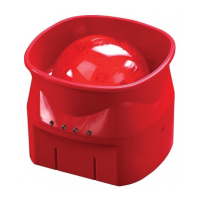
Fig 3. Discovery Open Area Voice Sounder
Fig 2. Example of Address 78
Fig 1. PCB outline
Analogue Values
Analogue Value Status Analogue Value Status
0 Flash Memory Fail 17 Sounder Volume 1*
1 Sounder Fail 18 Sounder Volume 2
2 Visual Indicator Fail 19 Sounder Volume 3
3 Sounder and Visual Indicator Fail 20 Sounder Volume 4
4 General Fault 21 Sounder Volume 5
22 Sounder Volume 6
23 Sounder Volume 7
*Volume 1 does not comply with the requirements of EN54-3
 Loading...