Discovery
®
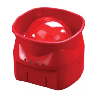
Open Area Voice Sounder
Installation Guide
General
This guide describes the installation of the following products:
Part Number Product Name Type Colour
58000-010 Discovery Open Area Voice Sounder with Isolator Indoor (Type A) Red
58000-020 Discovery Open Area Voice Sounder with Isolator Indoor (Type A) White
58000-030 Discovery Open Area Voice Sounder Visual Indicator
with Isolator
Indoor (Type A) Red
58000-040 Discovery Open Area Voice Sounder Visual Indicator
with Isolator
Indoor (Type A) White
Warning
The Discovery Open Area Voice Sounder requires compatible control panel software to
operate. Please check with the panel manufacturer for compatibility before installation.
Function*
The Open Area Voice Sounder Visual Indicator has 3 tone/message pairs, 7 volume set-
tings, independent control of sounder and visual indicator and fast turn-on functions. The
con guration of the sounder is set by the control panel. Please refer to the panel literature
for details.
Mounting the backbox
The backbox is removed by using an unlocking key to press in one of the retaining lugs.
The Open Area Voice Sounder has 6 slotted drillable holes in the backbox and can be
installed directly to the mounting surface.
Wiring Details
Note: This product is polarity sensitive (supply reversal protected) and will not function if
wired incorrectly.
Drill holes for cable entry as appropriate for the installation. Drill guides are marked on the
backbox. Connect the loop cables to the terminal block, observing polarity and func-
tional earth/screen if applicable. The wiring terminals accept solid or stranded cables up
to 2.5mm².
Commissioning
It is important that the device be fully tested after installation. Many fault conditions are
the result of simple wiring errors. Check all connections to the unit.
Setup and Test Mode
These modes allow volume adjustment and functional testing locally. In test mode no
volume adjustment is possible.
The required mode is entered via the control panel and is con rmed by a red setup LED
which ashes once a second. Sounder state is controlled by placing a magnet adjacent
to the ashing setup LED. When the con rmation LED ashes, withdraw the magnet. A suit-
able extendable magnetic wand is available, part no. 29650-001.
*The Visual Indicator function does not comply with the requirements of EN54-23
1
39214-601/2018/Issue 5
© Apollo Fire Detectors Limited 2012
Apollo Fire Detectors Limited, 36 Brookside Road, Havant, Hants, PO9 1JR, UK
Tel +44 (0)23 9249 2412 Fax +44 (0)23 9249 2754
Email: techsales@apollo- re.co.uk Website: www.apollo- re.co.uk
4
Tone Table
* These tones are EN54 compliant
Please note: Recording and loading of messages on this device cannot be made.
Synchronisation can be made by group or global mode from the panel when switching on or by address ‘0’ synchronisation.