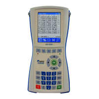
4.6.3 Maximum Demand Test
This page can be accessed from Load Values screen by pressing of F1, followed by F2 and F3.
Configuration of MD tests is in Test Settings menu, where Period, Subperiods and Window can be
specified. The duration of MD test is identical with Dial test duration and it is recommended to be at
least two times greater than period of MD test.
Test is started with F1 key. Then the Energy (E) is being summed and the average power (MD Act.) is
being calculated. Operator must be aware of the number already stored in electricity meter’s Maximum
Demand Register. It is highly advised to delete such meter’s register before and after MD test. This
operation will ease the whole test procedure.
During MD test the icon above F1 depicts the sign of play. In this state the test can be prematurely
stopped by F1 and the icon changes to stop sign. To evaluate the MD test, it is compulsory to wait until
the test stops automatically or at least wait until the time “End” passes because only then the “MD Reg.”
will obtain value different from zero. This is the value which is compared with the meter’s MD register.
When the test is ceased, “Enter MD register” message flashes until any key is pressed. This warning
informs the operator to submit the value of MD register from meter. Then the overall MD error is
calculated.
Dial Test runs always simultaneously with Maximum Demand Test which has to last longer than Dial
Test. The reason lies in principle of Dial Test evaluation. This feature offers also evaluation of these
two tests concurrently.
Meter connected to the network can measure quantities via transformer. In such case meter’s
parameters can be defined for transformer’s secondary side or calculated to the primary side (upper
switch – Sec / Prim). By default, both Prim. / Sec. switches and CT/VT ratios are acquired from
database. They can be changed (they turn red). These switches along with CT / VT ratios enable to set
where the meter is placed (during measurement) and where the device measures energy.
Content:
Prim. / Sec. .... Meter measures energy for primary or
secondary side of transformer (if applicable).
Default state is Sec.
MD ............. Register value from meter after the test
CT .............. Current Ratio
VT .............. Voltage Ratio
Prim. / Sec. .... Side of transformer on which is the
energy measurement carried out
Fixed Window ..... Actual window type
Error .......... Error calculated from MD and MD Reg.
MD Act. ..... Actual average power *
MD Reg. ... Power value obtained after defined time (End) *
E ................ Energy measured during the test *
* Last three quantities show two values with respect to Prim.
/ Sec. switches
Begin ......... MD test timestamp of beginning of window
End ............ Duration of the test in minutes
<Progress bar> ... Graphical interpretation of duration of the test