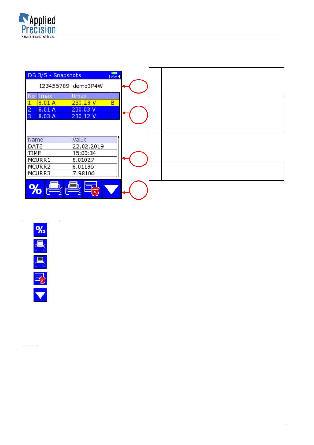
4.13.3 Database of Load Values
Database contains load point values saved for actual meter in Vector Diagram, Harmonics or Curve
pages.
Table of Load Points
• No. ........ load point number
• Imax ...... maximal current value
• Umax .... maximal voltage value
Table of Parameters of selected load point
• Name .... name of parameter
• Value ..... value of parameter
Control keys:
F1 ............................ Make new load point saving
F2 ............................ Print selected item only
F3 ............................ Print test report of selected meter to portable printer
F4 ............................ Delete selected item (load point)
F5 ............................ Switch to next database screen
▼▲ ......................... Navigation on screen or in table
PgDn, PgUp ............ Page selection within table
OK ........................... Confirmation of selected item
ESC ......................... Exit screen or close browsing table
Note:
Quantities U1 – U3 and I1 – I3 (3 phase system) are used when voltage and current probes are
connected to device.
Quantities Ua and Ub resp. Ia and Ib (3x for 3 phase system) are used when two voltage probes resp.
two current probes are connected to the device … “a” and “b” are designators of probe inputs.
See picture in chapter 3.4.



 To Next Page