EasyManua.ls Logo

APRI FBSN-4FD User Manual

APRI FBSN-4FD
5 pages
To Next Page IconTo Next Page
Page #1 background imageLoading...
Page #1 background image
1
4
5
8
9
10
2
4 x
4 x
4 x
1
0 x
P
R
I
M
R
3
M
4
2
9
8
U
V
1
1
2
4
FC
25
F1
55
k
m
/
h
7
4 x
+12V
km/h
1
1
+12/24V
3
3
3
F2
80
13
MUTE
MUTE
3
15
3
24
13
11
11
11
11
FBSN-4FD
MAIN UNIT
green
green
CONNECTION INSIDE THE CAR
black/yellow
FC
= Continuous tone
ZONE
distance (cm)
green
black/blue
brown
green
green
gray/red
yellow
blue
ZONES OF DETECTION
(FACRORY SETTINGS)
ELECTRONIC PARKING SYSTEM FBSN-4FD
SET CONTENTS
12
5
1
+
1
5
A
6
A
2
3
4
4 x
H = 400 - 500 mm
H
H = 500 mm
H = 650 mm
H = 350 mm
+10°
-10°
SENSORS INSTALLATION
18
8
green
green
100
100
!
!
+18°C
320
320
5
green
green
1 +
24
7
7
8
green
green
green
green
1
6
B
5
B
10
P
R
I
M
E
R
3
M
4
2
9
8
U
V
13
1
7
6
5 x
14
P
R
I
M
E
R
3
M
4
2
9
8
U
V
5
6
Question and Answer IconNeed help?

Do you have a question about the APRI FBSN-4FD and is the answer not in the manual?

APRI FBSN-4FD Specifications

General IconGeneral
BrandAPRI
ModelFBSN-4FD
CategoryAutomobile Electronics
LanguageEnglish

Summary

Sensors Installation

Sensor Installation Procedure

Details the process of mounting sensors, including bracket selection and hole drilling based on bumper height.

Cabling and Main Unit Installation

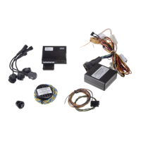
Illustrates routing front cable harness, connecting sensors, and placing the main control unit and speaker.

Detection Zones Overview

Presents factory default detection zones (FC, F1, F2) and their corresponding distances.

Description of the function

Automatic Sensor Deactivation

Front sensors automatically deactivate when vehicle speed exceeds approximately 10 km/h.

Manual Sensor Deactivation

Option to temporarily deactivate front sensors using a push-button, indicated by the button's light.

Time Window Activation Mode

Describes sensor activation timing based on ignition, reverse gear, or push-button, with deactivation after a set period.

Assembly guide

Detailed Sensor Mounting

Provides instructions for sensor installation into bumpers, including bracket use, painting, and primer application.

Detailed Cabling and Unit Installation

Explains routing sensor cables, connecting to ignition, chassis, speed signal, and MUTE, plus speaker and main unit placement.

Adjustment of parameters

Parameter Settings and Options

Lists adjustable parameters, their ranges, default settings, and notes, including volume, sensor ranges, and STOP zones.

Problems solving

Troubleshooting Faulty Sensors

Details how to identify faulty sensors via tone and display, and the importance of prompt replacement.

Resolving False Obstacle Alerts

Lists common causes for false alerts, such as frost or sensor placement, and their solutions.

Technical specifications

Related product manuals