Do you have a question about the APRILIA DORSODURO 2007 and is the answer not in the manual?
Details about identifying the vehicle's chassis and engine numbers for service and parts.
Technical data for the engine, including model, type, capacity, bore/stroke, and clearances.
Information on electrical components, fuses, bulbs, warning lights, and chassis structure.
Specifications for suspension travel, sizes, brake system components, and wheel/tyre information.
Details on the fuel system and a comprehensive list of tightening torques for various assembly units.
Tools for engine support, flywheel removal, and related engine component servicing.
Specialized tools for clutch bell locking, connecting rod locking, and valve spring compression.
Tools for engine internal work, including valve spring compressors and piston ring drivers.
Tools for diagnosing system errors and measuring pressures, such as Manometer and Tool Panel.
Detailed table of routine maintenance operations and intervals for various vehicle systems.
Procedures for inspecting, cleaning, and replacing spark plugs to ensure optimal engine ignition.
Instructions for checking engine oil level, replacing the oil filter, and performing oil changes.
Steps for accessing, removing, and maintaining the air filter for proper engine air intake.
Procedure for measuring and adjusting valve clearances to ensure correct engine valve timing.
Procedure for diagnosing problems indicated by the EFI warning light or abnormal engine behavior.
Diagnostic steps to identify and resolve issues preventing the engine from starting.
Diagram illustrating the location and layout of major electrical components on the motorcycle.
Information on relay locations in the wiring diagram and on the vehicle for electrical system service.
Essential checks for correct electrical connection and cable laying after system installation or repair.
Details on speed, throttle grip, intake pressure, engine temperature, air temperature, and lambda sensors.
Detailed pin-out configurations for the Marelli control unit and related sensors for diagnostic purposes.
Information on the CAN line communication protocol, its function, and troubleshooting for signal errors.
Steps to prepare the vehicle before engine removal, including disconnecting components.
Detailed instructions for safely detaching and removing the engine from the motorcycle chassis.
Step-by-step guide for correctly mounting and securing the engine back into the vehicle chassis.
Diagrams and procedures for disassembling, checking, and assembling the gearbox and its shafts.
Instructions for removing the clutch cover, disassembling, checking, and assembling the clutch plates.
Procedures for removing and servicing the cylinder head, valves, and overhead camshafts.
Details on crankcase components, crankshaft removal, inspection, and crankcase half assembly.
Steps for removing, inspecting, and installing the engine oil pump assembly.
Information on the fuel pump unit, its electrical characteristics, and troubleshooting relay control errors.
Explanation of the Ride by Wire system's logic, parameters, and control unit functions.
Instructions for removing the throttle body assembly, including filter casing and injector detachment.
Procedures for removing and checking the front wheel, bearings, and fork leg components.
Details on the steering bearing components and the procedure for adjusting play to ensure proper steering.
Procedures for removing and checking the rear wheel, chain, and shock absorbers.
Diagram and key for the swinging arm, detailing bearings, spacers, and removal procedures.
Procedures for adjusting drive chain tension, checking for wear, and proper lubrication.
Diagram and instructions for removing the exhaust manifold, tail pipe, and lambda sensor.
Details on front and rear brake calipers, including removal and replacement of brake pads.
Instructions for purging air from the hydraulic braking system to restore optimal braking efficiency.
Identifies components of the clutch system, including pump, lever, cylinder, and bleeding kit.
Diagram illustrating the cooling system layout, including radiator, expansion tank, pipes, and thermostat.
Steps for removing the electric cooling fan and the radiator assembly for service.
Procedures for overhauling the water pump, including cover, rotor, and control gear removal and refitting.
Procedures for removing and servicing the front headlight and rear taillight assemblies.
Instructions for removing footrests and side body panels, including associated fasteners.
Steps for removing the air box assembly and the fuel tank, including associated components.
Procedures for removing the instrument cluster support and the radiator cover.
Checks for vehicle appearance, tightening torques, and electrical system functionality.
Verification of all fluid levels and performance evaluation through a road test.
Comprehensive inspection of vehicle systems and static checks after a test drive.
Operations for two-seater approval compliance and fitting of hand guards.
| Year | 2007 |
|---|---|
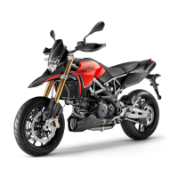
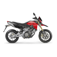
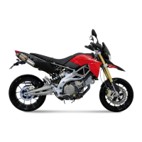
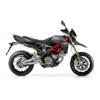
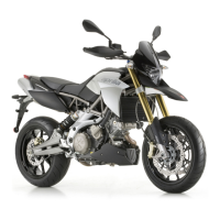
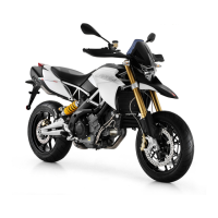
| Manufacturer | Aprilia |
| Model | Dorsoduro |
| Category | Motorcycle |
| Compression Ratio | 11.0:1 |
| Fuel System | Electronic Fuel Injection |
| Ignition | Digital electronic |
| Gearbox | 6-speed |
| Final Drive | Chain |
| Seat Height | 870 mm (34.3 inches) |
| Displacement | 749 cc |
| Bore x Stroke | 92 x 56.4 mm |
| Cooling System | Liquid |
| Rear Suspension | Monoshock |
| Front Brake | Dual disc |
| Rear Brake | Single disc |
| Torque | 82 Nm |
| Fuel Capacity | 12 liters |
| Power | 92 hp (67 kW) |