6
Aprimatic s.r.l.–Via Emilia 147- 40064 Ozzano dell’Emilia–Bo Italy–T.+39 051 69 60 711 / F.+39 051 69 60 722
1.0 CONSTRUCTION AND STANDARD REFERENCES
WARNING: CAREFULLY READ THE FOLLOWING INDICATIONS. FAILURE TO COMPLY WITH SOME OF
THESE MAY VOID THE PRODUCT WARRANTY.
1) During wiring operations, STRICTLY FOLLOW the connection diagram, a WRONG connection MAY DAMAGE the
system.
2) DO NOT USE STABLE position switches for the control.
3) DO NOT USE a cable longer than 50 m between CONTROL UNIT and SENSORS.
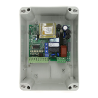
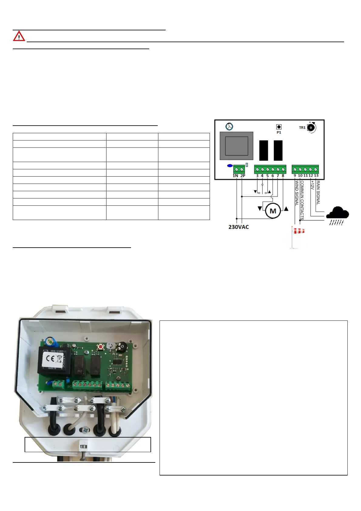
4) cable inlet MUST BE POSITIONED in the LOWER side of the container through the cable glands present in the
accessory pack (PICTURE 1)
5) position the control unit in a SUITABLE place, possibly near the motor.
6) The wired controls of the control unit are of the DEAD MAN type. Control inputs are LIVE.
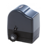
2.0 TECHNICAL DATA AND CONNECTION BOARD
MAXIMUM OUTPUT
2.25 A / Cos
2.25 A / Cos
IP44 IP44
DIMENSIONS 160 x 140 x 46
160 x 140 x 46
3.0 LAYOUTS AND ELECTRICAL WIRING
NOTE: It is recommended to install the control unit on the wall and in a vertical position, to maintain the declared
plastic container protection class. Installations other than those set out may compromise the correct protection of the
container and damage the operation of the board inside it. The manufacturer is not responsible for the control unit
malfunctioning if the installation has not been carried out as per the indications mentioned above.
The diagram below shows the correct routing of the power supply, motor and detector cables.
It is recommended to comply with the cable cross-sections indicated for the inputs.
NOTE Use the cable glands supplied with the control unit.
Ref. 1 – Power Supply input
Cable H05VV-F cross-section 2x1.5mm -(Not included)
Ref.2 – Upstroke and downstroke contact
Not powered
Cable 3x1mm (Not included)
Ref. 3 – Motor input
Cable with cross-section 3x1.5mm / 3x1mm depending on the
motor to control - (supplied with the motor)
Ref. 4 – Input of wind and/or rain detector sensors
Cable with cross-section 2x0.5mm * - (supplied with RV-N sensor)
Cable with cross-section 3x0.22mm * - (supplied with SP1-N
sensor)
* NOTE: for distances greater than the length of the supplied
cable, always use a shielded cable.
Ref. 1 2 3 4
Cable gland
 Loading...