smart
RSD-S-PLC Quick Installation Guide
Step1. Buckle RSD-S-PLC onto the PV module frame.
A.Back buckle
B.Front buckle
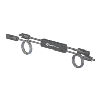
Step 2. Connect the input connectors of the RSD-S-PLC to the junction box, the device
output DC voltage is within the range of 0.6 to 1v.
NOTE: Do not short-circuit the RSD-S-PLC output connectors, otherwise it will be damaged.
2022/05/27 Rev2.8 | Quick Installation Guide1
Mounting brackets
INPUT- INPUT+
OUTPUT- OUTPUT+
NOTE: Do not place the RSD-S-PLC (including DC connectors) where exposed to the sun, rain or snow, even gap
between modules. Allow a minimum of 3/4’’(1.5cm.) between the roof and the bottom of the RSD-S-PLC
to allow proper air flow.