Do you have a question about the APsmart RSD-S-PLC and is the answer not in the manual?
Crucial safety guidelines for installation and operation, plus definition of qualified personnel.
Explanation of symbols used in manuals and on equipment to indicate hazards.
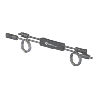
Features and functionality of the APsmart RSD-S-PLC rapid shutdown device.
Features and specifications of the APsmart Transmitter-PLC.
Features and specifications of the APsmart Transmitter-PLC Outdoor Kit.
Features and specifications of the APsmart Transmitter-PLC-PCBA.
Explains the APsmart rapid shutdown system's operation with RSD-S-PLC and Transmitter-PLC.
Essential notes and compliance requirements for installing the RSD-S-PLC.
Lists necessary additional components and tools for completing the RSD-S-PLC installation.
Instructions on how to mount the RSD-S-PLC using front or back buckles on the PV module frame.
Guide for connecting RSD-S-PLC output to a junction box and input to the system.
Instructions for connecting the RSD-S-PLC output to the inverter via a DC extension cable.
Important notes for installing the Transmitter-PLC and its power supply.
Explains the meaning of Power LED and Signal LED during Transmitter operation.
Drilling guide for enclosures using .75" conduit for single and dual core configurations.
Drilling guide for enclosures using 1" conduit for single and dual core configurations.
Product codes and descriptions for ordering APsmart Transmitter units.
Product codes and descriptions for ordering APsmart RSD-S-PLC units.
The APsmart Rapid Shutdown System (RSD-S-PLC) is a critical component in photovoltaic (PV) installations, designed to enhance safety by providing rapid shutdown capabilities for solar modules. This system is engineered to comply with stringent safety regulations, specifically NEC 2017 (690.12) requirements, which mandate the rapid de-energization of PV systems in emergency situations. The primary function of the RSD-S-PLC is to ensure that PV modules quickly cease power output when a rapid shutdown event is initiated, thereby protecting first responders and maintenance personnel from high-voltage hazards.
At its core, the RSD-S-PLC operates by continuously receiving a "heart-beat" signal from an APsmart Transmitter-PLC. This signal acts as a lifeline, indicating that the system is operating normally and that PV modules can continue to supply energy. In the absence of this signal, whether due to a manual shutdown or a system fault, the RSD-S-PLC automatically triggers a rapid shutdown mode. This mechanism ensures that the PV array's voltage is reduced to a safe level within seconds, as required by safety standards. The system's compliance with SunSpec requirements further underscores its adherence to industry-recognized communication and control protocols for rapid shutdown, ensuring interoperability and reliability.
The APsmart rapid shutdown system is comprised of several key components, each playing a vital role in its overall functionality. The RSD-S-PLC unit itself is installed at the PV module level, typically mounted on the module frame. Its robust design allows it to withstand harsh environmental conditions, making it suitable for a wide range of outdoor installations. The unit features both input and output ports for DC connections, facilitating its integration into the PV string. The physical installation involves buckling the RSD-S-PLC onto the PV module frame, a process that can be performed using either front or back buckles, offering flexibility in mounting.
Complementing the RSD-S-PLC is the APsmart Transmitter-PLC, which serves as the control hub for the rapid shutdown system. The Transmitter-PLC is responsible for generating and sending the continuous heart-beat signal to all connected RSD-S-PLC units. This device is available in several configurations to suit different installation needs. The standard Transmitter-PLC unit is designed for indoor use and can be equipped with either a single or dual core, allowing it to manage multiple PV strings. It also offers optional power supply configurations, supporting both 85-264VAC for residential applications and 180-550VAC for commercial projects.
For outdoor installations, the Transmitter-PLC Outdoor Kit provides a comprehensive solution. This kit includes a Transmitter-PLC unit, an outdoor enclosure, and a power supply (either 85-264VAC or 180-550VAC), ensuring that the control unit is protected from environmental elements while maintaining its functionality. The enclosure is designed to be weather-resistant, making it ideal for rooftop or ground-mount systems where the Transmitter-PLC needs to be located outdoors. Additionally, for integrated solutions, the Transmitter-PLC-PCBA (Printed Circuit Board Assembly) is available. This version includes the core components of the Transmitter-PLC, allowing it to be integrated directly into other equipment, such as inverters, for a more streamlined system architecture. Like the other Transmitter-PLC variants, it supports single or dual cores and various power supply options.
A crucial aspect of the Transmitter-PLC's operation is its power supply, which must be on the same AC branch circuit as the inverter. This ensures that if the inverter's AC power is disconnected, the Transmitter-PLC also loses power, thereby initiating a rapid shutdown across the entire PV array. During normal operation, the Transmitter-PLC features a Power LED that should be lit and a Signal LED that should be blinking, indicating that the heart-beat signal is being transmitted successfully. If the Signal LED is not blinking, it suggests a potential issue with the Transmitter, while an unlit Power LED points to a problem with the power supply.
The system wiring diagram illustrates how these components are interconnected. The RSD-S-PLC units are connected in series with the PV modules, and their outputs are then connected to a junction box. The Transmitter-PLC, in turn, is connected to the inverter, typically via a self-made DC extension cable, ensuring that the control signal is properly integrated into the overall PV system. The cores of the Transmitter-PLC are designed to allow either the positive or negative homerun wires from the PV array to pass through them, enabling the transmission of the rapid shutdown signal. The number of strings that can be managed by a single core depends on the DC cable diameter, with different capacities for various cable sizes.
Installation of the RSD-S-PLC involves several steps to ensure proper functionality and safety. Before any electrical work begins, it is imperative to disconnect both the solar module and the inverter from the electrical grid. All installations must adhere to local electrical codes and technical regulations. Only qualified professionals should undertake the installation or replacement of RSD-S-PLC units. It is also crucial to verify that the voltage and current specifications of the PV modules align with those of the RSD-S-PLC, and that the PV module's DC operating voltage falls within the allowable input voltage range of the RSD-S-PLC. The maximum open circuit voltage of the PV module must not exceed the specified maximum input voltage of the APsmart RSD-S-PLC.
During installation, installers should be aware of the risk of electric shock and avoid touching any live parts of the system, especially when it is connected to the electrical grid. The body of a running RSD-S-PLC can reach high temperatures as it acts as a heat sink, so caution is advised to prevent burns. The RSD-S-PLC is not designed for user repair; in case of failure, customers should contact APsmart Customer Support for an RMA number and replacement, as attempting to repair or open the unit will void the warranty.
Maintenance of the APsmart rapid shutdown system primarily involves ensuring that the Transmitter-PLC is functioning correctly, as indicated by its LEDs. Regular checks of the power supply and signal transmission can help identify and address potential issues proactively. The system is designed for long-term reliability, with robust components built to withstand the demands of PV installations. The rapid shutdown system label should be placed no more than 1 meter (3 feet) from the Transmitter or AC disconnect, ensuring that emergency personnel can quickly identify the rapid shutdown initiation point.
In summary, the APsmart rapid shutdown system provides a crucial safety layer for PV installations, enabling rapid de-energization of solar modules in compliance with modern safety standards. Its design, encompassing the RSD-S-PLC at the module level and various Transmitter-PLC configurations, offers flexibility and reliability for both residential and commercial projects. Proper installation and adherence to safety guidelines are paramount to ensure the system's effective operation and the safety of personnel.
| Model | RSD-S-PLC |
|---|---|
| Operating Voltage | 90-280V AC |
| Communication | PLC |
| Connector Type | MC4 |
| Input Voltage | 90-280V AC |
| Protection Features | Over Voltage, Over Temperature |