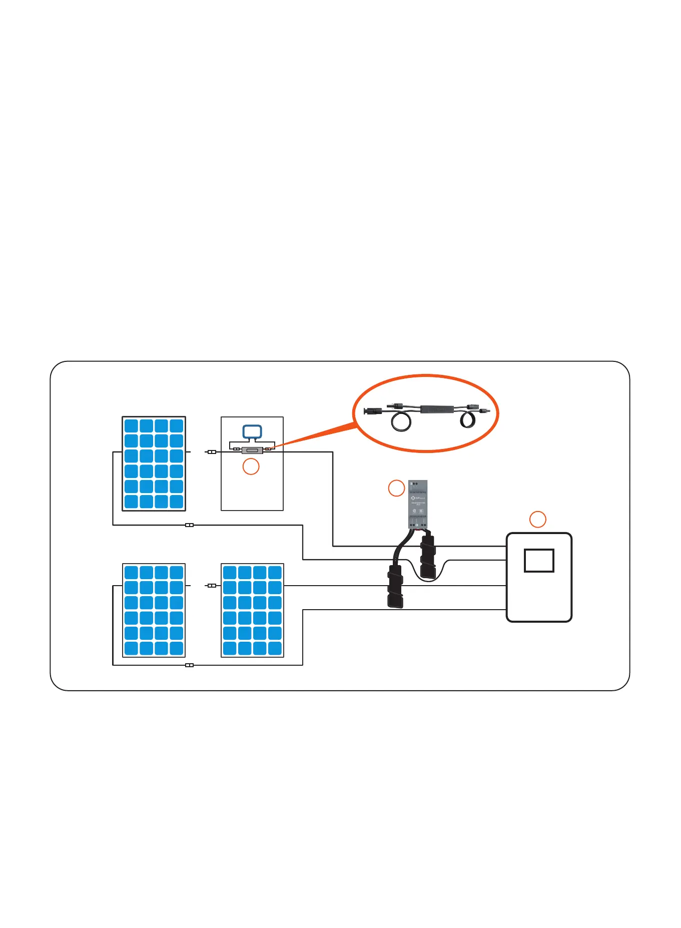
SYSTEM WIRING DIAGRAM
① RSD-S-PLC
② Transmitter-PLC
③ Inverter
The APsmart Rapid Shutdown System Transmitter-PLC is part of a rapid shutdown solution when
paired with APsmart RSD-S-PLC, a PV module rapid shutdown unit. While powered on, the
Transmitter-PLC sends a signal to the RSD-S-PLC units to keep their PV modules connected and
supplying energy.
RSD-S-PLC units automatically enter rapid shutdown mode when the Transmitter-PLC is switched
o and resume energy production when power is restored to the Transmitter-PLC. This solution
complies with NEC 690.12 specifications for 2017 and supports the SunSpec signaling for rapid shut-
down.
The Transmitter-PLC includes one or two cores and an optional power supply: 85-264VAC for
residential, 180-550VAC for commercial.
Transmitter-PLC Outdoor Kit includes a Transmitter-PLC with one or two Cores, outdoor enclosure,
85-264VAC or 180V-550VAC power supply. It could be used in residential or commercial project.
The Transmitter-PLC-PCBA includes one or two cores and an optional power supply: 85-264VAC for
residential, 180-550VAC for commercial.
4
- +
- +
- +
- +
- +
- +
- +
- +
- +
- +
- +
- +
- +
- +
2
3
1
…
…
…