©Aqua Logic, Inc. 2017
Page 3 of 5
9558 Camino Ruiz.
San Diego, CA 92126
PH: 858.292.4773 Fax: 858.292.0537
Email: info@aqualogicinc.com
Website: www.aqualogicinc.com
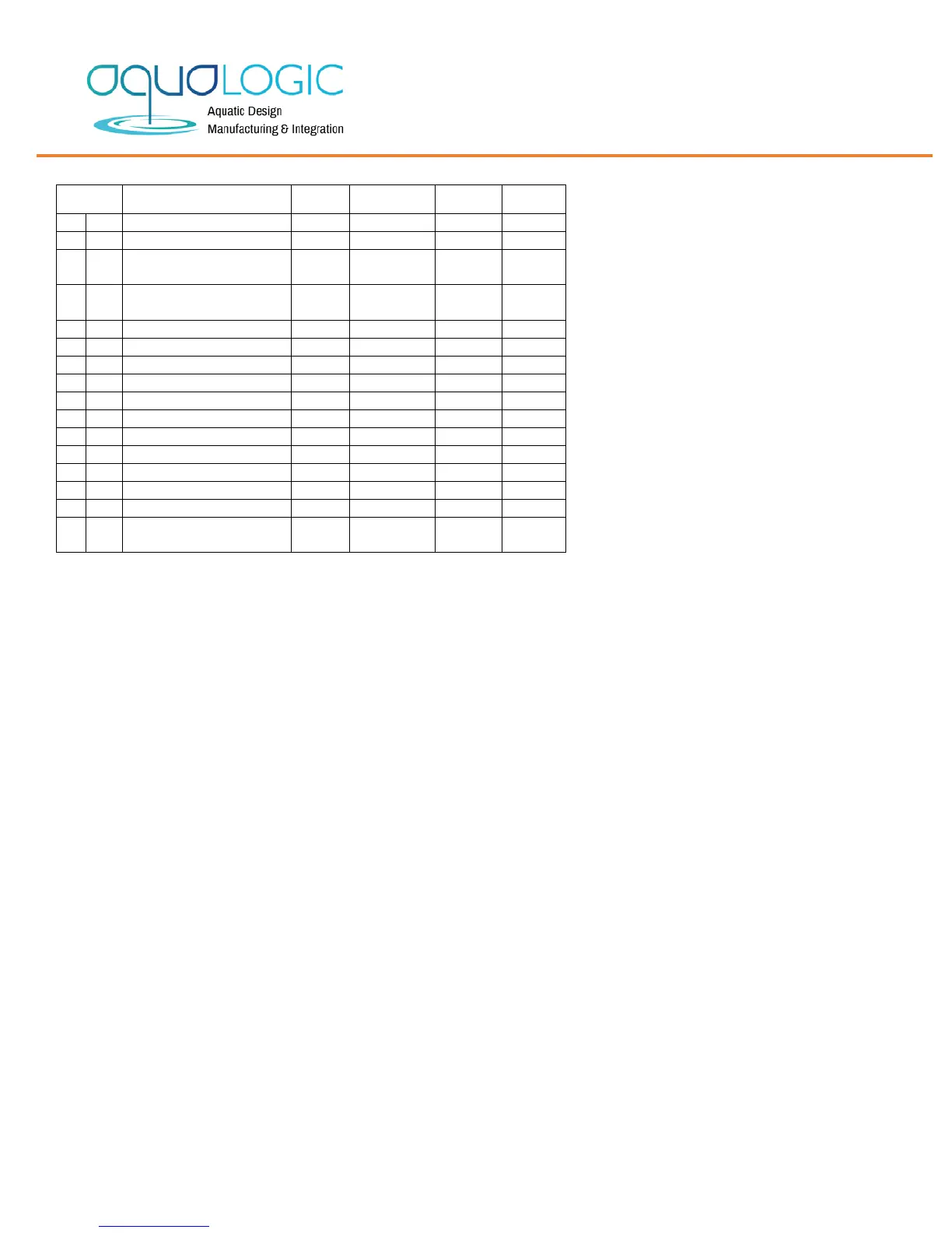
DC SINGLE STAGE TEMPERATURE CONTROL PROGRAMMABLE PARAMETERS TABLE
Parr. Description Units Range
Differential / Hysteresis
r1 Lower value set point Degrees
-50 to 302 °F
30°F
r2 Higher value set point Degrees
-50 to 302 °F
100°F
Interval Time between Defrosts
Min. time stop for compressor
Temperature scale selection
t0 Max. temperature on display Degrees
-50 to 302 °F
100°F
PARAMETER DESCRIPTIONS
SP = Set Point. Temperature desired to regulate the machine. Can vary
from r1 to r2.
r0 = Differential. Heating: If temperature is ≥ SP then output is OFF. If
temperature is < SP - r0 then output is ON. Cooling: If temperature is ≥
SP + r0 then output is ON. If temperature is < SP then output is OFF.
r1 = Lower Set Point Limit.
r2 = Upper Set Point Limit.
d0 = Heat or Cooling Control. Ht = heating control, Co = cooling control.
d2 = Not used
d8 = Not used.
c0 = Minimum Time for Compressor to be OFF. Minimum time for the
compressor to stop until it can start again.
c1 = Continuous Cycle Time. The remaining time for a continuous cooling
cycle.
c2 = ON Time of fault cycle, during probe error.
c3 = OFF Time of fault cycle, during probe error.
P0 = Selection of Engineering units between F and C.
P1 = Ambient Probe Calibration. Offsets temperature in degrees to
adjust the ambient probe.
H5 = Access Code to Parameters. Factory-set to 0.
H6 = Selection of Input Probe Type: PTC or NTC.
t0 = Temperature Display Limit. Maximum temperature shown on the
display, although the real temperature can be greater.
OPERATION IN CASE OF ERROR
If the probe or thermostat memory should fail, the chiller or heater will turn off.
Error Messages
In normal operation, the probe temperature will be shown. In case of alarm press the “SET” and the “DOWN” ▼ arrow buttons at the
same time to quit the alarm. An error messages will be shown:
• Er – Memory error
• -- Shorted –circuited probe error
• oo- Open probe


 To Next Page
 Loading...