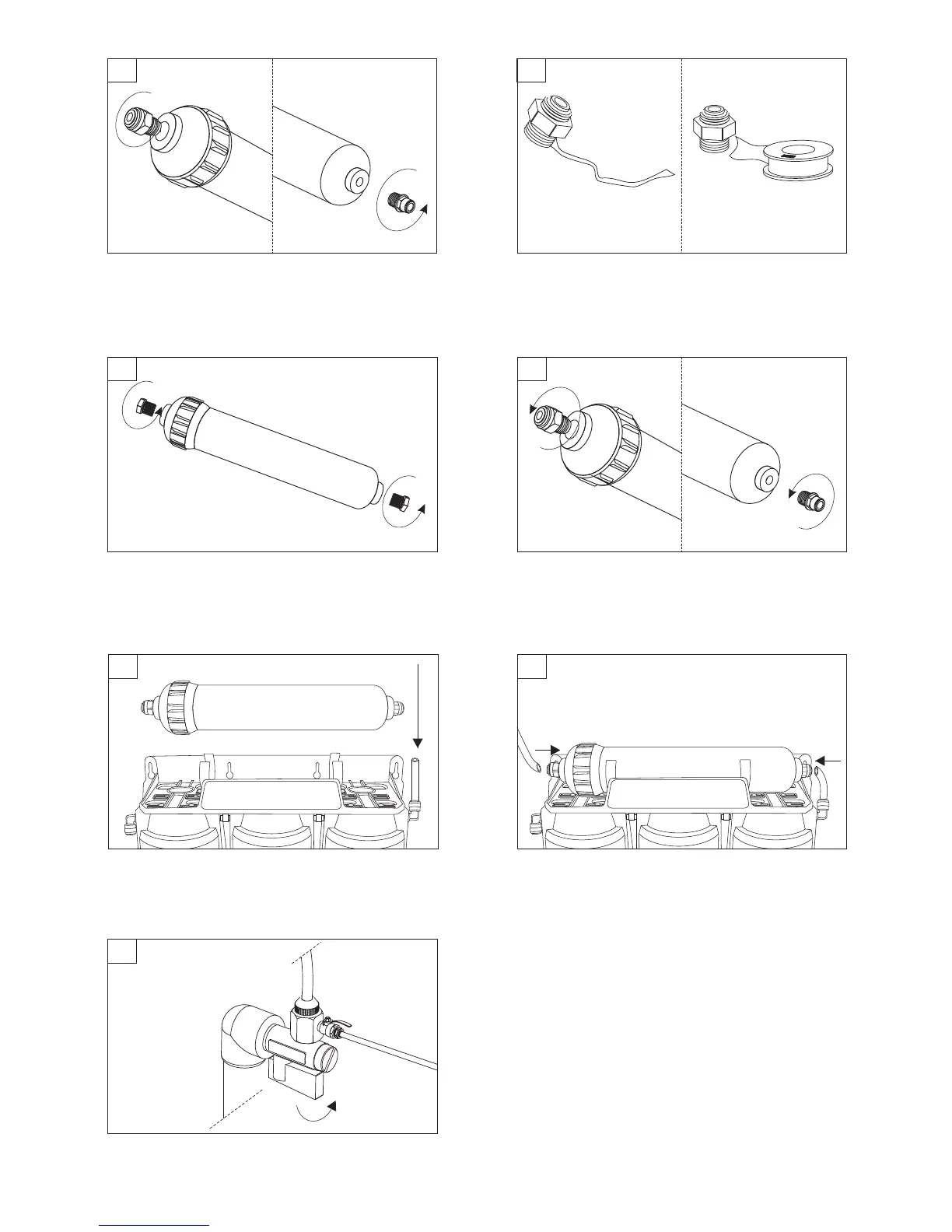
Unscrew inlet and out let connectors from the membrane. Remove all layers of old Teflon tape and apply mutliply
layers of new one.
NOTE! Ensure that Telflon tape is winded in the
opposite direction to the direction connector will be
installed.
6
Unpack new UF membranes element and unscrew its inlet
and outlet end caps.
5
7
Connect inlet and outlet connectors to the housing of new
UF membrane.
NOTE! Do NOT remove elbow connector after the
installation has been started. Stopping and removing
(unscrewing) the element may result in inadequate
connection and water leak.
8
16
11
9
10
Push in UF membrane housing into mouting clips.
WARNING! While installing hollow fiber membrane,
remember to keep the proper direction of water flow
(indicated by an arrow on membrane sticker).
Insert flexible tubing (all the way) into both ends of UF
membrane.
! Check if inlet/outlet tubings are correctly and
firmly connected. Make sure the tubing is not bent.
NOTE
Open water supply valve.
WARNING! UF membrane is soaked with a special
conserving solution.
Install the cartridge in the direction of flow, then rinse it for
several minutes before use. Use only with water
microbiologically safe and adequately disinfected.
 Loading...