EasyManua.ls Logo

Araknis Networks 210 Series - User Manual

Araknis Networks 210 Series
18 pages
Print Icon
To Next Page IconTo Next Page
Loading...
210 SERIES NETWORK SWITCHES
Quick Start Guide
AN-210-SW-F/R-8-POE
AN-210-SW-F/R-16-POE
AN-210-SW-F/R-24-POE
AN-210-SW-F-48-POE
Question and Answer IconNeed help?

Do you have a question about the Araknis Networks 210 Series and is the answer not in the manual?

Summary

FCC Warning

UL Statement and Compliance

SFP Port Requirements

SFP ports require UL Listed Optional Transceiver product, rated 3.3Vdc, Laser Class 1.

Electrical Safety and Earthing

Class I equipment must be earthed; power plug requires properly wired earth ground socket outlet.

Welcome and Series Overview

Series Overview

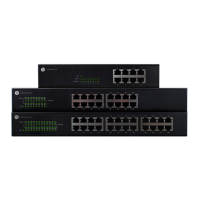
Details the models, Ethernet ports, SFP ports, and PoE budget for the Araknis 210-series switches.

Step 1: Unbox

Step 2: Install

Rack Mount Installation

Instructions for mounting the switch in a standard equipment rack using included ears.

Wall Mount Installation

Guidance on wall mounting, including orientation and recommended wall types; notes on specific models.

Shelf Mount Installation

Details on placing the switch on a shelf or flat surface.

Step 3: Connect

Step 4: PoE Budget

Step 5: Verify Status

Power LED Indicator

Indicates the status of the system: On means the system is up, Off means it is down.

1 Gbps LED Indicator

Shows connection speed: On for 1000Mbps, Off for 10/100Mbps.

Link;Act LED Indicator

Indicates device connection and activity: On for connected, Blinking for data transfer, Off for disconnected.

Step 6: Connect to OvrC Account

Step 7: Log into Web Interface

Find IP Address via OvrC

Locate the switch's IP address within the OvrC customer device list for access.

Access Switch via Web Browser

Use a web browser to navigate to the switch's IP address on the same local network.

Default Login Credentials

Use 'araknis' for both username and password to log into the switch's web interface.

Other Access Methods: DHCP IP Address

Other Access Methods: Default IP Address

Configure Default IP Access

Modify Network Adapter Settings

Change network adapter settings to configure access to the switch's default IP.

Set TCP;IPv4 Properties

Configure the Internet Protocol Version 4 (TCP/IPv4) properties for the network connection.

Access Switch via Default IP

Input IP and Subnet Mask

Enter the IP address and subnet mask into the TCP/IPv4 properties for the connection.

Login with Default Credentials

Access the switch via its default IP address and log in with default credentials.

Pro Tip: Resetting the Switch

Warranty and Contact Information

Overview

The Araknis Networks 210 Series Network Switches are a line of managed network switches designed to provide Gigabit connectivity across all ports, featuring modern aesthetics and a user-friendly interface. These switches are suitable for various network setups, offering different port configurations and Power over Ethernet (PoE) budgets to accommodate diverse needs.

Function Description:

The Araknis 210 Series switches are designed to facilitate high-speed data transfer within a network. They provide multiple Ethernet ports for connecting devices and SFP (Small Form-Factor Pluggable) ports for fiber optic connections, enabling flexible network expansion. The PoE-enabled models can deliver power to compatible devices such as IP cameras, wireless access points, and VoIP phones directly over the Ethernet cable, simplifying installation and reducing cable clutter. The managed interface allows for advanced network configuration, monitoring, and troubleshooting.

Important Technical Specifications:

Models and Port Configurations:

  • AN-210-SW-F/R-8-POE: 8 Ethernet Ports, 2 SFP Ports, 65W PoE Budget
  • AN-210-SW-F/R-16-POE: 16 Ethernet Ports, 2 SFP Ports, 130W PoE Budget
  • AN-210-SW-F/R-24-POE: 24 Ethernet Ports, 2 SFP Ports, 190W PoE Budget
  • AN-210-SW-F-48-POE: 48 Ethernet Ports, 4 SFP Ports, 375W PoE Budget

PoE Standards:

All PoE models support both PoE (802.11af) and PoE+ (802.11at) standards, allowing for compatibility with a wide range of PoE-powered devices. The total PoE budget for each model limits the maximum power that can be delivered across all PoE ports, with a per-port consumption limit of 30W.

Connectivity:

  • Gigabit Ethernet on all ports.
  • SFP ports for fiber optic or RJ45 SFP adapters (sold separately).

Physical Characteristics:

The switches come with options for front-facing or rear-facing ports (indicated by F/R in the model name) and include rack-mount ears for installation in a standard network rack. Rubber feet are also provided for flat surface placement.

Regulatory Compliance:

  • FCC Warning: Complies with Part 15 of the FCC Rules, designed for commercial environments. Users in residential areas may need to correct interference at their own expense.
  • CE Warning: Class A product. Users in domestic environments may need to take adequate measures to address potential radio interference.
  • UL Statement: All models are evaluated by UL. Intended for indoor use only and should not be connected to an Ethernet network with outside plant routing. Requires Class I optical transceivers conforming to U.S. code of federal regulation, 21 CFR 1040. Equipment is only to be connected to PoE networks without routing to outside plants.
  • Earthing: Class I Equipment, must be earthed. The power plug must be connected to a properly wired earth ground socket outlet to prevent hazardous voltages on accessible metal parts.

Usage Features:

Installation:

The switches can be installed in three ways:

  1. Rack Mount: Using the included rack-mount ears and screws.
  2. Wall Mount: The switch must be wall-mounted with Ethernet ports facing either the floor or the ceiling. For the AN-210-SW-F-48-POE, wall mounting is possible but not recommended. Mounting should be into a thick plywood/concrete wall using M5*20mm screws by a skilled professional.
  3. Shelf Mount: Placed on a flat surface using the provided rubber feet.
  • Important Note: Do not stack other equipment on top of the switch to avoid interference or damage.

Connectivity:

  • Connect the switch to a router, IP cameras, computers, and other network devices using Ethernet cables.
  • SFP ports can be used with Araknis SFP adapters for RJ45 or multi-mode fiber cables for extended reach or specific network requirements.

PoE Budget Management:

Users must calculate the total power consumption of all connected PoE devices to ensure it does not exceed the switch's PoE budget. Each port has a maximum consumption limit of 30W.

Status Indicators:

The switches feature LEDs to indicate their operational status:

  • Power LED: On (system up), Off (system down).
  • 1Gbps LED: On (port connected at 1000Mbps speed), Off (port connected at 10/100Mbps speed).
  • Link/Act LED: On (port connected to another device), Blinking (packets running through the port), Off (port not connected to a device).

Remote Management (OvrC):

The switches integrate with OvrC, a cloud-based remote management platform. OvrC allows for:

  • Remote firmware upgrades.
  • Real-time notifications.
  • Intuitive customer management from a computer or mobile device.
  • Plug-and-play setup without port forwarding or DDNS address requirements. To connect to OvrC, the switch needs internet access. Users log into OvrC (www.ovrc.com or OvrC app) and add the device using its MAC address and Service Tag numbers.

Local Web Interface Access:

  • Via OvrC: Find the switch's IP address in the OvrC interface, then open a web browser on the same LAN and navigate to the IP address.
  • DHCP IP Address: If not connected to OvrC, the IP address can be found by checking the router's client table or using a network scanner (e.g., Fing), where the manufacturer will display "Araknis."
  • Default IP Address (192.168.20.254): If the switch doesn't receive an IP address from DHCP or needs to be accessed offline, a computer can be configured with a static IP address (e.g., 192.168.20.2) and subnet mask (255.255.255.0) to directly connect to the switch's default IP.
  • Default Credentials: Username: araknis, Password: araknis.

Maintenance Features:

Reset Options:

  • Reboot: Press and hold the RESET button for 5 seconds, then release. The switch will power cycle, and front status lights will flash.
  • Factory Reset: Press and hold the RESET button for 10-15 seconds until the status LEDs flash once. The switch will power cycle and be reset to factory default settings.

Firmware Upgrades:

Firmware upgrades can be performed remotely via the OvrC platform, ensuring the device stays up-to-date with the latest features and security patches.

Warranty and Support:

The product comes with a 2-Year Limited Warranty. Details are available at snapav.com/warranty. Technical support can be reached at (866) 838-5052, or via email at techsupport@snapav.com. Additional legal resources and patent information are available at snapav.com/legal.

Araknis Networks 210 Series Specifications

General IconGeneral
BrandAraknis Networks
Model210 Series
CategorySwitch
LanguageEnglish

Related product manuals