10
AC Power / VARS Operating Procedure
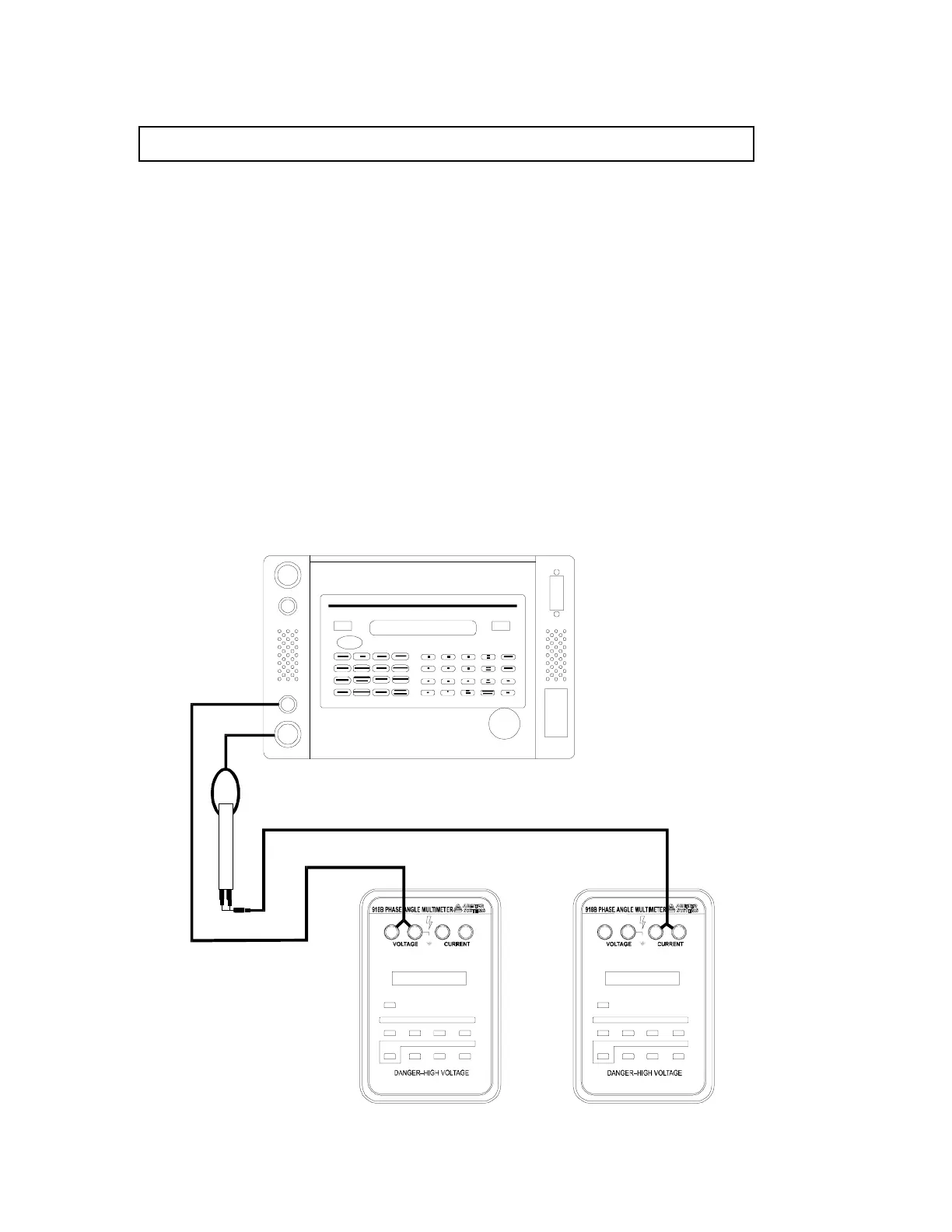
CAUTION: Prior to making any connections, place the PMC in Standby Mode.
Connect the Model 918B to the PMC as shown below and perform the following steps:
1. Press 60 or 400 HZ.
2. Press POWER.
3. Press VOLTAGE.
4. Enter the desired voltage using the keypad and the units key.
5. Press CURRENT.
6. Enter the desired current using the keypad and the units key.
7. Press POWER. The power calculated from the entered voltage, current, and phase
values will be displayed. Press POWER again and VARS will be displayed. Note that
modifying Power or VARS changes the current output while leaving the voltage and
phase fixed.
8. Press OPER.
9. MODIFY, MEMORY, or % DEV may be used. POWER, VARS, CURRENT,
VOLTAGE or FREQUENCY may be modified. Note that modifying Power changes
the current output while leaving the voltage fixed.
10. To remove the output signal, press STBY when the measurement is complete.
+
+
1000 Vrms
1000 Vdc
45 - 500
CT OUTPUT ONLY
25 mArms MAX
25V
MAX
POWE
AT PO WE R ON
USE "HOLD" KEY TO CHANGE CT
USE "PHASE" KEY TO CHANGE PHASE
Vdc VA
RANG
rm
rm W/Wh HOL
SHIF
PHAS
PF
STAR
PHAS
FRE
MIN/MA
∆
CURRENT TRANSFORMER TERMINALS ARE AT
POTENTIAL AS (–) VOLTAGE
USE PROPER
FUSED
AUX .
REMOT
OLTAG
CURRE
1040C PANEL METER
OVERLO
HIG
VOLTAG
POWE
GP-
O SRQ ORMT
OLSN O RLK
Arb
iter
Sy
ste
ms
10
00:
1
CT
+
+
1000 Vrms
1000 Vdc
45 - 500
CT OUTPUT ONLY
25 mArms MAX
25V
MAX
POWE
AT PO WE R ON
USE "HOLD" KEY TO CHANGE CT
USE "PHASE" KEY TO CHANGE PHASE
Vdc VA
RANG
rm
rm W/Wh HOL
SHIF
PHAS
PF
STAR
PHAS
FRE
MIN/M
∆
CURRENT TRANSFORMER TERMINALS ARE AT
POTENTIAL AS (–) VOLTAGE
USE P ROPER
FUSED

 Loading...