11
Power Factor / Phase Operating Procedure
CAUTION: Prior to making any connections, place the PMC in Standby Mode. The
following procedure employs initial output values of 120 volts and 5 amps at 60 Hz and
0°, 30° and 60° phase values. A full meter calibration would include other values.
The Phase Convention in the PMC is determined by the following equations:
Voltage: V(t) = Vo sinωt
Current: (t) = Vo sin (ωt + Θ )
Power: Vrms Irms cos Θ
VARS: Vrms Irms sin ( -Θ)
Power Factor: Cos Θ
Where: Θ = phase angle in degrees between voltage and current.
Phase Angle Sign of Power Sign of VARS Power Factor
0 < Θ ≤ 90 + - Lead +
90 < Θ ≤ 180 - - Lead -
-180 < Θ ≤ -90 - + Lag -
-90 < Θ ≤ 0 + + Lag +
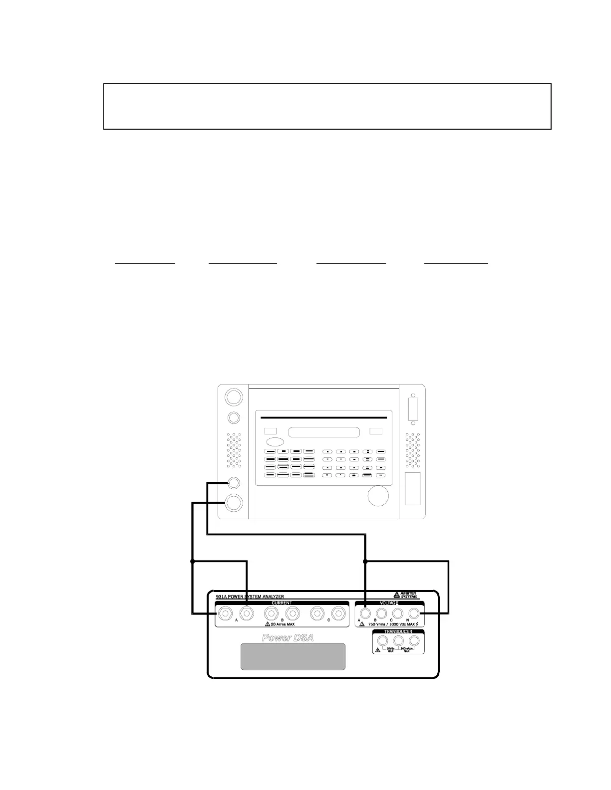
Turn-OFF the PMC and connect to the Model 931A System Analyzer as shown below and
perform steps of Table 1:
AUX.
REMOT
OLTAG
CURRE
1040C PANEL METER
OVERLO
HIG
VOLTAG
POWE
GP-
O SRQ ORMT
OLSN O RLK
™
 Loading...
