4
7.1 TECHNICAL SPECIFICATIONS 30
7.2 DIMENSIONS 31
7.3 WIRING DIAGRAM 31
7.4 WARRANTY 34
1 Transport & handling
1.1 Transport
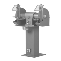
E 312 Industrial grinding machine is delivered mounted on a pallet packed in
protective wrapping.
1.2 Handling
E 312 Industrial grinding machine is portable in the packing in which it is
delivered. If the grinding machine is supplied with a pedestal please note that the
pedestal is safely secured to the transport pallet.
1.3 Placing
Placing of the industrial grinder must take place on a firm and level ground.
Tighten the grinding machine to the floor or the work table by using the four holes
used for securing the machine to the pallet.
The wiring of the machine must be performed within the given range on the motor
sign.
The machine must be wired according to the Wiring diagram (see section 6.3).
The wiring must be performed by an authorized electrician. Make sure that the
motor (and eventually KU 12-exhaust system) has the correct direction of rotation
(see the arrow on the cover).
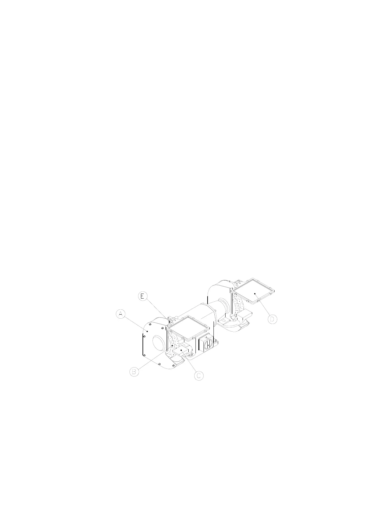
Fig.: 1.1
Control before use that the outer cover (A) (see fig.: 1.1) is solidly mounted to the
inner cover. The outer cover must be mounted during operation. Only have the
outer cover dismounted during changing the grinding wheel. The grinding wheel
(B) must be able to rotate freely without being loose. The tool rest (C) must be
adjusted to a distance of appr. 2 mm from the grinding wheel.
The eye shield (D) must be clean and adjusted to the right position and the spark
arrester (E) is adjusted to a distance of appr. 5 mm from the grinding wheel and
lightly tightened.