Do you have a question about the ARDETEM DIP 400 and is the answer not in the manual?
Physical dimensions of the instrument case and terminal layout.
Details for panel cut-out dimensions and mounting procedures.
Information on front face, housing, and terminal protection ratings.
Material and safety rating of the instrument housing.
Description of rear connectors, including type and screw terminal size.
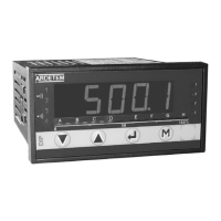
Specifications for the display, including points, color, and alarm LEDs.
Wiring diagrams for process, temperature, resistance/potentiometer, and logic inputs.
Wiring diagrams for voltage passive current, active current, digital, and relay outputs.
How the instrument communicates via front face keys and LEDs.
Navigation keys and conventions for interacting with the programming menus.
Overview of the main menu structure and access to different functions.
Method for entering numerical values and parameters using the front panel keys.
Structure of the programming menu accessed via input, display, analog output, and communication parameters.
Detailed settings for configuring the various input types (Process, Temperature, Resistance).
Configuration for temperature inputs, including thermocouple types and cold junction compensation.
Configuration for resistance and potentiometer inputs, including calibration ranges.
Settings for display parameters like decimal point, resolution, and linearisation.
Configuration for digital output communication, including slave number, speed, and parity.
Programming of logic inputs, including functions like display hold and reset.
Configuration for relay outputs, including setpoint modes, hysteresis, and time delays.
Meter's self-monitoring for drifts, errors, and overstepping.
Detection and handling of sensor rupture conditions for relays and analog output.
Option to disable sensor rupture detection for specific inputs.
Assignment of functions to optional LEDs 5 through 8.
Details on input types, their limits, accuracy, and associated programming.
Configuration for digital output communication via RS485, including protocol and format.
How to read the instrument's configuration parameters.
Security settings for protecting meter configuration and functions.
Procedure for setting a new access code to secure the instrument.
Accessing functions like display simulation and analog output simulation.
How to clear recorded alarm history.
Procedure to remove or suppress a programmed tare value.
Displaying min/max values and deleting them using single key presses.
Operations like display shifting, visualization of direct measure, and alarm setpoint adjustment.
Adjusting the display's down scale and full scale values.
Viewing the raw input signal without processing.
How to view and modify alarm thresholds.
Procedure for setting a tare value for specific input types.
Indicates when the measured value exceeds the input range.
Signifies a break or disconnection in the input sensor.
Indicates when a set value falls outside the allowed parameters.
Reports internal meter faults or calibration issues.
Signals input values exceeding the maximum or falling below the minimum thresholds.
Mapping of Modbus register addresses to instrument parameters.
Mapping of addresses, formats, and units for specific instrument versions.
Details on Modbus functions for reading and writing data.
Explanation of the Cyclic Redundancy Check algorithm for data integrity.
| Display Type | TFT LCD |
|---|---|
| Power Supply | 24 VDC |
| Communication Ports | USB, Ethernet |
| Operating Temperature | 0°C to 50°C |
| Display Size | 10.1 inches |