p3
Protection:
Front face: IP 65
Housing: IP20
Terminals: IP 20
Housing:
Self-extinguishing case of
black UL 94 V0 ABS.
2. SPACE REQUIREMENTS
Dimensions of the case: (with terminals)
96 x 48 x 124 mm
Panel mounting
cut out 44 x 91 mm
external
seal
Holding panel
max. thickness 30
case
tightenings
Terminals
General features
• Sampling time: 100 ms
• Input impedance
≥ 1 MΩ for the voltage inputs
Max. drop 0.9 V max. for the voltage input
• Common mode rejection rate: 130 dB
Serial mode rejection rate: 40 dB 50/60 Hz
• Zero drift compensation and self-calibration
• Insulation: input / power supply: 2.5 kV eff. 50Hz-1min
Input / output: 2.5 kV eff. 50Hz-1min
• Universal power supply:
20...270 VAC and 20 ...300 VDC 50/60/400 Hz
• Power draw
: 4 W max. 7.5 VA max.
• Conform with the standards IEC 61000-6-4 on rejections and
IEC 61000-6-2; on immunity (industrial environment)
IEC 61000-4-2 level 3, IEC 61000-4-3 level 3,
IEC 61000-4-4 level 4, IEC 61000-4-6 level 3.
CE marking according to the directive 2004/108/CE
Connectors plug-off connectors on
rear face for screwed connections
(2,5mm², flexible or rigid)
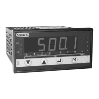
Display: ±10 000 points (14 mm)
Electroluminescent red (green optional)
4 alarm leds
+ 4 leds with programmable functions
-10 000/+100 000 points (14 mm)
(optional)
-2 000 / +10 000 points (20 mm)
(consult)
Programming
• Via the keyboard
• With the configuration software SUPERVISION
To communicate with the series
DIP400/DIP402 you will need a con-
nection cable (M4 USB). To connect this cable to the DIP, insert the
DIN contact into the especially foreseen female connector (on the
instrument side). Then connect the USB cable to a PC. The software
SUPERVISION allows reading the measures or modifications of the
meter configuration.
Each configuration is kept as a file stored on disk. These files can then
be consulted, modified, duplicated or loaded into the meters. The files
can be created with or without having a meter connected. This software
also allows the saving of existing configurations from the instruments
which are already in service. All the files can be edited on any type of
printer.
 Loading...