EasyManua.ls Logo

Arduino NRF24L01 User Manual

Arduino NRF24L01
14 pages
To Next Page IconTo Next Page
Page #1 background imageLoading...
Page #1 background image
Arduino Wireless Communication –
NRF24L01 Tutorial
Dejan Nedelkovski
Arduino Tutorials
36
In this Arduino tutorial we will learn how to make a wireless communication between two
Arduino boards using the NRF24L01 transceiver module. You can watch the following
video or read the written tutorial below.
Overview
For explaining the wireless communication we will make two examples, the first one will be
sending a simple “Hello World” message from one Arduino to another, and in the second
example we will have a bi-directional communication between the Arduino boards, where
using the Joystick at the first Arduino we will control the servo motor at the second
Arduino, and vice versa, using the push button at the second Arduino we will control the
LED at the first Arduino.
NRF24L01 Transceiver Module
Let’s take a closer look at the NRF24L01 transceiver module. It uses the 2.4 GHz band
and it can operate with baud rates from 250 kbps up to 2 Mbps. If used in open space and
with lower baud rate its range can reach up to 100 meters.
Question and Answer IconNeed help?

Do you have a question about the Arduino NRF24L01 and is the answer not in the manual?

Arduino NRF24L01 Specifications

General IconGeneral
Maximum Data Rate2 Mbps
Number of Channels125
InterfaceSPI
Data Rate250kbps, 1Mbps, 2Mbps
Operating Voltage1.9V - 3.6V
Current Consumption11.3mA transmitting, 12.3mA receiving
RangeUp to 100 meters (open space)
Dimensions15mm x 29mm

Summary

NRF24L01 Connections to Arduino

Arduino Codes for Wireless Communication

Example 1 Transmitter Code

Provides the Arduino code for the transmitter in the first example.

Example 1 Receiver Code

Provides the Arduino code for the receiver in the first example.

Code Description and Logic

Bi-directional Wireless Communication Example

Example 2 Source Codes

Example 2 Transmitter Code

Provides the Arduino code for the transmitter in the second example.

Example 2 Receiver Code

Provides the Arduino code for the receiver in the second example.

Bi-directional Communication Logic Details

Joystick to Servo Control Logic

Details sending joystick data to control a servo motor.

Button to LED Control Logic

Explains receiving button state to control an LED.

NRF24L01 Comprehensive Specifications

NRF24L01 Pinout Table

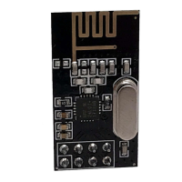
Details the pinout and connections to different Arduino boards and libraries.

Wiring Diagrams

Related product manuals