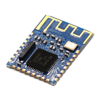
Solution: ADD bypass capacitors across GND and 3.3V ON the radio modules or use the
Base Modules shown above. One user said, "Just Solder a 100nF ceramic cap across the
gnd and 3.3v pins direct on the nrf24l01+ modules!" Some have used a 1uF to 10uF
capacitor.
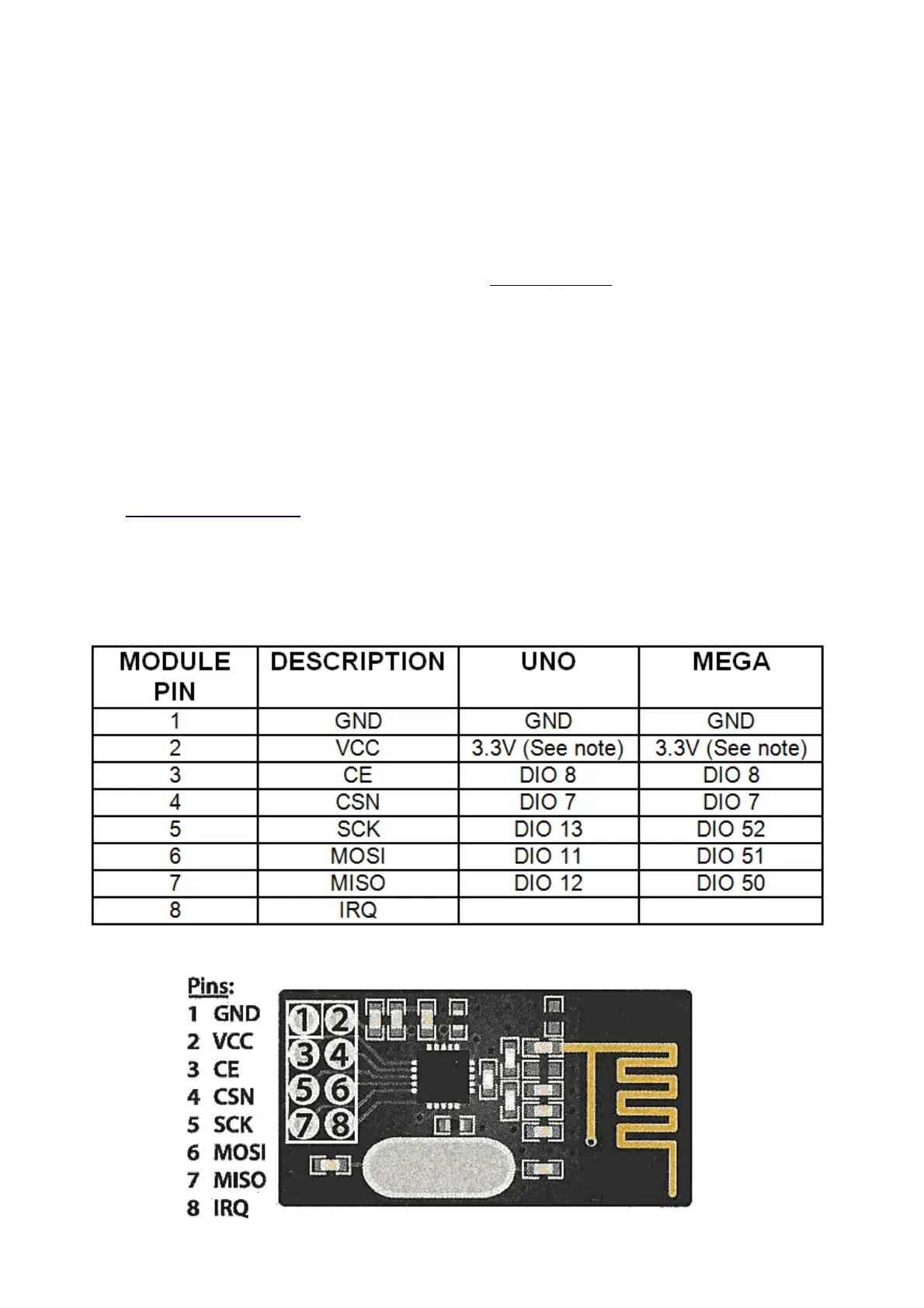
• NOTE: Pin 8 IRQ is Unused by most software, but the RF24 library has an example
that utilizes it.
The COLOR is for optional color-coded flat cable such as THIS. Photos above show an
example.
NOTE: These units VCC connection must go to 3.3V not 5.0V, although the Arduino itself
may run at 5.0V and the signals will be OK. The NRF24L01+ IC is a 3.3V device, but its
I/O pins are 5 V tolerant , which makes it easier to interface to Arduino/YourDuino.
Arduino UNO and earlier versions have a 3.3V output that can run the low-power version
of these modules (See Power Problems at the top of this page!), but the high-power
versions must have a separate 3.3V supply or use a Base Module with a 3.3V regulator.
The YourDuino RoboRED has a higher power 3.3V regulator and can be used to run the
high-power Power Amplifier type module without a separate 3.3V regulator.
Source :
https://arduino-info.wikispaces.com/Nrf24L01-2.4GHz-HowTo
 Loading...