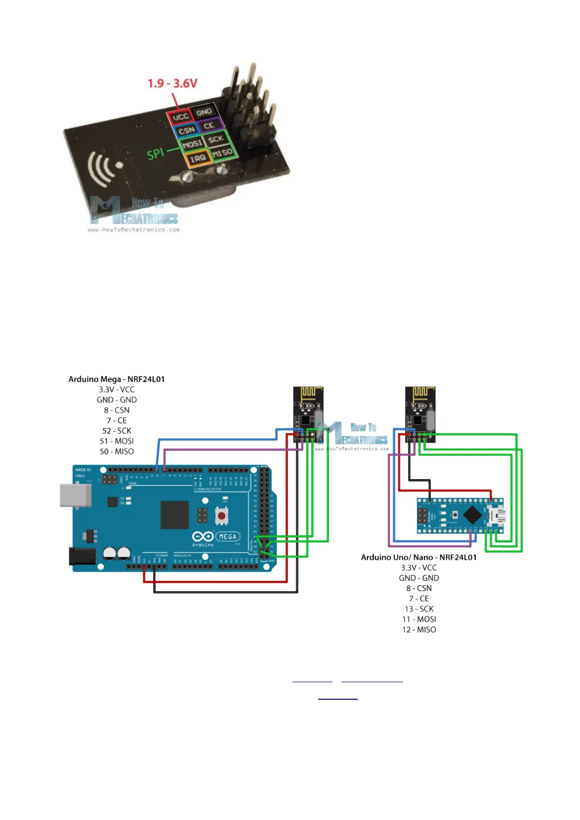
Three of these pins are for the SPI communication and they need to be connected to the
SPI pins of the Arduino, but note that each Arduino board have different SPI pins. The pins
CSN and CE can be connected to any digital pin of the Arduino board and they are used
for setting the module in standby or active mode, as well as for switching between transmit
or command mode. The last pin is an interrupt pin which doesn’t have to be used.
So once we connect the NRF24L01 modules to the Arduino boards we are ready to
make the codes for both the transmitter and the receiver.
You can get the components needed for this Arduino Tutorial from the links below:
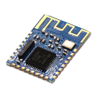
• NRF24L01 Transceiver Module…………. Amazon / DealExtreme
• Arduino Board ………………………………… Amazon
 Loading...