• 3 x 6 Header (White/Red/Black)
• A0 / 5V / Ground
• A1 / 5V / Ground
• A2 / 5V / Ground
• A3 / 5V / Ground
• A4 / 5V / Ground
• A5 / 5V / Ground
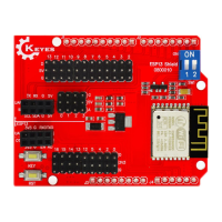
There is also a 3-pin blue header that that brings out 5V, ground and D2 that can be used for a digital sensor
or other remote connection
• 1 x 3 Header (Blue)
• G = Ground
• ‘+‘ = 5V
• S = D2 – digital I/O
• RGB LED
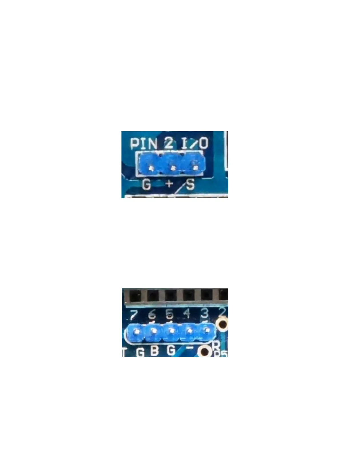
And for good measure, there is a 5-pin header that brings out D3, D5, D6, 5V and Ground. This puts 3
PWM outputs along with power and ground on a single connector which can be handy for several things
like driving an RGB LED.
• 1 x 5 Header (Blue)
• ‘ ‘ = 5V – This pin is unmarked but sits next to D7
• B = D6 – B could be used for Blue on RGB LED
• G = D5 – G could be used for Green on RGB LED
• ‘-‘ = Ground
 Loading...