EasyManuals Logo

Arduino WiFI Shield User Manual

Arduino WiFI Shield
11 pages
To Next Page IconTo Next Page
To Previous Page IconTo Previous Page
Page #3 background imageLoading...
Page #3 background image
board to which it is attached. If you are using the shield with an older board, you need to connect the
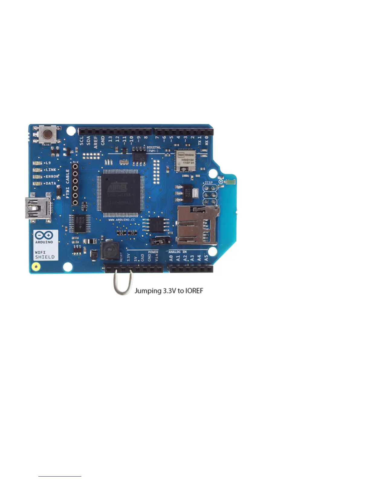
shield's IOREF pin to 3.3V. You can do this either with a jumper wire connecting IOREF to 3.3V as
shown in the photo below, or by soldering the IOREF jumper on the bottom of the shield, shown
below. WARNING: If you use the solder jumper, do not connect the shield to a rev3 or later board.
To be safe, remove the IOREF pin on the shield. Otherwise, you will be shorting 3.3V to 5V through
the IOREF pin.
Jumping 3.3V to IOREF (recommended)
Soldering 3.3V to IOREF

Questions and Answers:

Question and Answer IconNeed help?

Do you have a question about the Arduino WiFI Shield and is the answer not in the manual?

Arduino WiFI Shield Specifications

General IconGeneral
Operating Voltage5V
WiFi ChipsetHDG104
WiFi Standard802.11 b/g
Input Voltage5V
WiFi ModuleHDG104
EncryptionWEP, WPA
Connection with ArduinoSPI
MicrocontrollerN/A (Shield)
Digital I/O PinsN/A (Shield)
PWM ChannelsN/A (Shield)
Analog Input ChannelsN/A (Shield)
DC Current per I/O PinN/A (Shield)
Flash MemoryN/A (Shield)
SRAMN/A (Shield)
EEPROMN/A (Shield)
Clock SpeedN/A (Shield)
SecurityWEP, WPA

Related product manuals