23
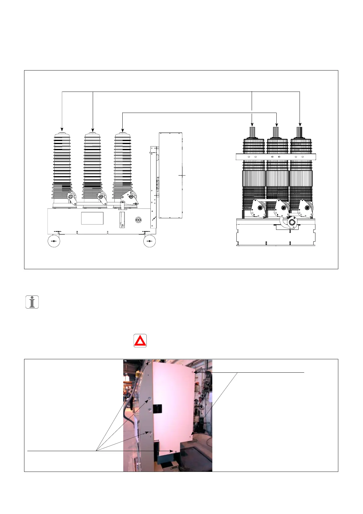
10.3 Lay-out of the poles on the circuit breaker's frame
The leading" pole is the pole
directly connected to the control
mechanism;
The led" pole is a pole which is
driven by the leading" pole.
Led" poles
Leading" poles
Longitudinal lay-out Front view lay-out (front face)
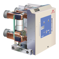
10.4 Remove the accessories for the wthdrawable circuit breakers
The accessories are to be
kept aside to equip the new
pole.
Screens
Whenever a moving part is
provided with screens, it is
necessary to remove them.
Square insulating nuts can
under no circumstances be
replaced by steel nuts.
4 square insulating nuts,
10 mm spanner
Fixing point for the screens.
8 steel bolts,
13 mm spannner