EasyManua.ls Logo

Argo AUR210CL Series - User Manual

Argo AUR210CL Series
29 pages
Print Icon
To Next Page IconTo Next Page
Loading...
TECHNICAL DATA & SERVICE MANUAL
ROOM AIR CONDITIONER WITH REMOTE CONDENSER
TEST
OFF ON
- AUR210CLXXXX
- AU213CLXXXX
- AUR310HLXXX
COOLING ONLY VERSION(R407C)
HEAT PUMP VERSION(R407C)
0.8180.090.1 05/2000
Question and Answer IconNeed help?

Do you have a question about the Argo AUR210CL Series and is the answer not in the manual?

Summary

Specifications

Unit Specifications

Detailed technical specifications for each model's unit.

Major Component Specifications

Specifications for indoor unit components like PCB, fan, transformer.

Indoor Unit Component Specifications

Specifications for indoor unit components like overload relays, capacitors, relays.

Outdoor Unit Specifications

Specifications for outdoor unit components like fan motor, safety devices.

Operating Range

Cooling Models Operating Range

Cooling operating temperature ranges for indoor and outdoor units.

Heat Pump Models Operating Range

Heat pump cooling/heating operating temperature ranges for indoor/outdoor units.

Dimensional Data

Indoor Unit Dimensions

Physical dimensions of the indoor unit.

Outdoor Unit Dimensions

Physical dimensions of the outdoor unit.

Performance Charts

Cooling Characteristics

Cooling performance curves based on ambient and indoor temperatures.

Heat Pump Cooling Characteristics

Cooling performance curves for heat pump models.

Heat Pump Heating Characteristics

Heating performance curves for heat pump models.

Refrigerant Flow Diagram

Cooling Models Flow Diagram

Refrigerant flow path for cooling-only models.

Heat Pump Models Flow Diagram

Refrigerant flow path for heat pump models.

Functions

Room Temperature Control (Cooling)

How room temperature is controlled in cooling mode.

Room Temperature Control (Heating)

How room temperature is controlled in heating mode.

Freeze Prevention

Function to prevent the indoor heat exchange coil from freezing.

Overload Prevention (Heating)

Function to prevent overheating of the indoor heat exchange coil.

Advanced Functions

Dry Operation (Dehumidification)

Dehumidification function using cooling cycle at low level.

Automatic Switching (Cooling;Heating)

Auto mode switching between cooling and heating.

Defrosting Operation (Heat Pump)

Operation to remove frost from the outdoor heat exchanger.

Defrosting Mode Timing Chart

Timing sequence for defrosting mode operation.

Electric Wiring Diagrams

Cooling Only Version Wiring

Wiring diagrams for cooling-only models.

Heat Pump Version Wiring

Wiring diagrams for heat pump models.

Troubleshooting

Initial Troubleshooting Checks

Initial checks before performing detailed troubleshooting.

Air Conditioner Does Not Operate

Troubleshooting steps when the air conditioner does not operate.

Circuit Breaker Trips

Troubleshooting for circuit breaker tripping issues.

Troubleshooting - Operation Issues

Water Level Alarm & Drainage Issues

Troubleshooting for condensate drainage system malfunctions.

No Outdoor Unit or Compressor Operation

Troubleshooting for no outdoor unit or compressor operation.

Partial Operation Failures

Troubleshooting when only specific parts of the unit do not operate.

Specific Component Failures

Troubleshooting for indoor fan, outdoor fan, or compressor motor failures.

Troubleshooting - Performance Issues

Abnormalities in Operation (Heat Pump)

Troubleshooting operational abnormalities in heat pump models.

Mode Switching & PCB Checks

Troubleshooting mode switching and indoor PCB issues.

Fuse & Setting Temperature Checks

Troubleshooting indoor PCB fuses and temperature setting issues.

Poor or Excessive Cooling;Heating

Troubleshooting poor or excessive cooling or heating performance.

Troubleshooting - Sensor Issues

Sensor Defects

Troubleshooting for defective temperature sensors (TH1, TH2).

Refrigerant Charge Restoring

Refrigerant Quantities

Specified refrigerant quantities for various models and configurations.

Vacuuming Procedures

Procedures for vacuuming indoor and outdoor units.

Electrical Component Checks

Insulation Resistance Measurement

Procedures for measuring insulation resistance of electrical parts.

Fuse Continuity & Capacitor Checks

Procedures for checking fuse continuity and motor capacitors.

Overview

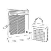
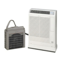
This document serves as a technical data and service manual for the Argo Ulisse series of room air conditioners with remote condensers. The series includes the Ulisse 10 (AUR210CLXXX), Ulisse 13 (AUR213CLXXX), and Ulisse HL (AUR310HLXXX) models. The Ulisse 10 and 13 are cooling-only versions (R407C refrigerant), while the Ulisse HL is a heat pump version (R407C refrigerant).

Function Description

The Ulisse air conditioners offer several operational functions:

Room Temperature Control (Cooling and Heating)

Room temperature is controlled by cycling the compressor ON and OFF based on readings from the room temperature sensor in the remote control unit. The remote control unit transmits temperature and other information to the indoor unit's controller every 3 minutes.

  • Thermo ON: When the room temperature is above the set temperature (T) + 1°C, the compressor turns ON.
  • Thermo OFF: When the room temperature is equal to or below the set temperature (T)°C, the compressor turns OFF.
  • Compressor Protection: The control circuit prevents the compressor from turning ON until it has been OFF for at least 3 minutes, allowing internal pressure to equalize. It also switches the compressor OFF after 5 minutes or more of continuous operation as a protective measure.

Freeze Prevention (Cooling)

This function prevents the indoor heat exchange coil from freezing. If the compressor has been running for 10 minutes or more and the indoor heat exchange coil temperature falls below -1°C, the control circuit stops the compressor for at least 6 minutes.

Overload Prevention (Heating)

This function prevents overheating of the indoor heat exchange coil during heating operation.

  • If the indoor heat exchange coil temperature rises above 59°C and the indoor fan is at low speed (L), the fan speed automatically increases to medium speed (M).
  • If the indoor heat exchange coil temperature rises above 61°C, the outdoor fan stops.

Dry Operation (Dehumidification) (Heat Pump Model)

Dry operation utilizes the cooling cycle to remove moisture from the air without significantly lowering the room temperature. The air conditioner automatically cycles ON and OFF based on room temperature.

  • Dry A1 Zone: When room temperature is T+2°C, the compressor operates intermittently (ON for 5 minutes, OFF for 5 minutes). The indoor fan operates at low speed (L) or stops intermittently while the compressor is ON.
  • Dry B Zone: When room temperature is T to T-T1°C, the compressor operates intermittently (ON for 5 minutes, OFF for 5 minutes). The indoor fan operates at low speed (L) or stops intermittently while the compressor is ON.
  • Monitor Zone: When room temperature is 15°C, both indoor and outdoor units stop.
  • Note: Intermittent ventilation involves switching the indoor fan speed between low speed and STOP. Dry operation does not occur when the room temperature is under 15°C. When the compressor stops, the indoor fan also stops.

Automatic Switching Between Cooling and Heating (Heat Pump Model)

In auto mode, the microprocessor calculates the difference between the set temperature and the room temperature to automatically switch between cooling and heating modes.

  • Room Temp. >= Set Temp.: Cooling operation begins.
  • Room Temp. < Set Temp.: Heating operation begins.

Defrosting Operation (Heat Pump Model)

When frost on the outdoor heat exchanger reduces unit capacity during heating, the microcomputer-controlled temperature sensing system detects the temperature drop gradient and initiates defrosting. During defrosting, indoor and outdoor fan motors stop, only the compressor operates, and the system temporarily switches to cooling operation mode.

Important Technical Specifications

Unit Specifications

  • Power Source: 220-240V ~ 50Hz
  • Refrigerant: R407C
  • Voltage Range: 198-264V
  • Controls: Microprocessor / I.C. Thermostat, Wireless remote control unit
  • Airflow Direction (Indoor): Horizontal (Manual), Vertical (Manual)
  • Air Filter: Washable, easy access
  • Compressor Type: Rotary (hermetic)
  • Refrigerant Control: Capillary tube
  • Noise Level (Indoor): 44/40/39 dB-A (Hi/Me/Lo) for AUR210CLXXX/AUR310HLXXX, 46/42/41 dB-A for AUR213CLXXX
  • Noise Level (Outdoor): 54 dB-A for AUR210CLXXX, 51 dB-A for AUR213CLXXX/AUR310HLXXX
  • Standard Tubing Length: ~2.5 m (extension kits available for ~4.5 m and ~6.5 m)
Model Capacity (Cooling) BTU/h (W) Capacity (Heating) BTU/h (W) Power Input (Cooling) W Power Input (Heating) W C.O.P. (Cooling) W/W C.O.P. (Heating) W/W Net Weight (Indoor/Outdoor) kg
AUR210CLXXX 9500 (2650) N/A 980 N/A 2.70 N/A 44 / 9.5
AUR213CLXXX 12500 (3670) N/A 1300 N/A 2.82 N/A 44 / 15
AUR310HLXXX 9820 (2800) 10700 (3140) 940 950 2.98 3.31 44 / 15

Major Components Specifications

  • Controller P.C.B.: Microprocessor, 250V - 3A control circuit fuse.
  • Fan & Fan Motor (Indoor): Cross-flow type, 1 x Ø100/L410 mm, 27W nominal output.
  • Transformer: Primary AC 235V - 50Hz, Secondary 11V - 0.727A (8VA) for cooling models, 19V - 0.526A (10VA) for heat pump model.
  • Power Relay (Compressor): AC 230V/220V/24V coil rated.
  • Thermistors:
    • Coil Sensor (TH1): Resistance varies with temperature (e.g., 6.5 kΩ at 20°C).
    • Room Sensor (TH2): Resistance varies with temperature (e.g., 5.0 kΩ at 25°C).
  • Compressor (Rotary hermetic): Nominal output 950W (AUR210CLXXX/AUR310HLXXX) or 1290W (AUR213CLXXX).
  • Safety Devices: Overload relays (OLR, OLR1, OLR2) with various trip temperatures and currents.
  • Run Capacitors: 1.0 μF (AUR210CLXXX/AUR310HLXXX) or 1.5 μF (AUR213CLXXX) for indoor unit; 2.0 μF (AUR210CLXXX) or 2.5 μF (AUR213CLXXX/AUR310HLXXX) for outdoor unit.
  • Drain Pump: AC 230V - 50Hz, 12W nominal output.
  • Solenoid Valve (4-way valve): AC 240-50Hz - 6W (Heat Pump models only).
  • Heat Exchanger Coil: Aluminium plate fin / Copper tube, 2 rows.

Dimensional Data

  • Indoor Unit: Height 790 mm, Width 580 mm, Depth 245 mm.
  • Outdoor Unit: Height 435 mm (490 mm for Heat Pump and AUR213CLXXX), Width 440 mm (525 mm for Heat Pump and AUR213CLXXX), Depth 230 mm (250 mm for Heat Pump and AUR213CLXXX).

Usage Features

  • Remote Control: The unit is operated via a wireless remote control unit, allowing for convenient adjustment of settings.
  • Timer Function: Includes a 24-hour ON/OFF timer and program function.
  • Fan Speed Control: Offers 3 fan speeds plus an auto setting for both indoor and outdoor fans.
  • Airflow Adjustment: Manual adjustment for horizontal and vertical airflow directions.
  • Washable Air Filter: Easy to clean for consistent performance.

Maintenance Features

Troubleshooting

The manual provides systematic charts for diagnosing common issues:

  • Circuit Breaker Trips/Fuse Blows: Guides through checking capacity, compressor/fan motor winding resistance, and insulation resistance.
  • Unit Not Running: Steps to verify power supply, circuit breaker status, and fuses on PCB assemblies.
  • Water-Level Alarm Flashing: Addresses issues with condensate drainage, including obstructions in the drain pipe and pump malfunctions.
  • Outdoor Unit/Compressor Not Running: Checks for thermo OFF conditions, freeze prevention, and proper setting temperature.
  • Partial Operation Failure: Specific checks for indoor fan, outdoor fan, and compressor motor failures, including capacitors, windings, and overload relays.
  • Abnormal Operation (Heat Pump): Troubleshoots issues with switching between heating/cooling, PCB defects, and remote control unit functionality.
  • Poor/Excessive Cooling or Heating: Guides through checking remote control unit placement, tubing insulation, refrigerant charge, air filter cleanliness, and fan speed settings.
  • Sensor Defects: Provides detailed flowcharts for diagnosing defective indoor coil temperature thermistor (TH1) and room temperature thermistor (TH2), including alarm signals and operational changes.

Checking Electrical Components

  • Insulation Resistance Measurement: Instructions for checking insulation resistance of power supply wires, indoor unit, and individual electrical parts using an insulation tester. A resistance exceeding 1 MΩ indicates good insulation.
  • Fuse Continuity Check: Steps to remove and check the continuity of fuses on the PCB assemblies using a multimeter.
  • Motor Capacitor Check: Procedure to test motor capacitors (compressor and fan motors) by observing multimeter pointer deflection and return, indicating capacitor health.

Refrigerant Charge Restoration

Detailed instructions for reloading the R407C refrigerant charge, including specific quantities for standard units and units with 2m or 4m extension kits.

  • Vacuum Procedure: Emphasizes the importance of creating a vacuum in the indoor unit and outdoor unit (little bag) to 10 mm Hg. abs.
  • Connection Devices: Recommends using specific connection devices (spare parts code 383092901) for quick and safe connection to the vacuum pump.
  • Precaution for Disassembly: A warning to run the compressor for 5 minutes before disconnecting the outdoor unit to prevent refrigerant leakage and to apply anti-freeze oil to rapid couplings.
  • Sealing Check: Advises checking the sealing of connections after restoring the freon charge and after joining the units.

Argo AUR210CL Series Specifications

General IconGeneral
BrandArgo
ModelAUR210CL Series
CategoryAir Conditioner
LanguageEnglish

Related product manuals