V
Victoria NelsonJul 30, 2025
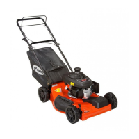
What to do if my Ariens Lawn Mower will not crank?
- HHannah JohnsonJul 30, 2025
If your Ariens Lawn Mower will not crank, charge or replace the battery.
What to do if my Ariens Lawn Mower will not crank?
If your Ariens Lawn Mower will not crank, charge or replace the battery.
Overview of the service manual's purpose and usage, emphasizing safe operation.
Information on how Ariens communicates service updates and technical bulletins to dealers.
Explanation of safety symbols and their meanings, emphasizing hazard awareness.
Guidelines for safe operation, including general and slope safety practices.
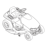
Identification and description of the unit's various controls and operational features.
Instructions for safely refueling the unit with fuel, including warnings.
Step-by-step guide for performing an engine oil change, including interval recommendations.
Steps to correctly adjust the neutral position of the hydro transmission.
Checks and adjustments for proper front wheel alignment and steering performance.
Chart to diagnose and resolve common engine operational issues and their causes.
Procedure for safely removing the engine from the unit frame.
Chart to diagnose and resolve issues related to the hydro transmission system.
Step-by-step guide for safely removing the hydro transmission assembly.
Detailed instructions for performing major internal repairs on the hydro transmission.
Chart to diagnose and resolve common gear transmission problems.
Detailed steps for disassembling the gear transaxle for inspection or repair.
Procedure for removing the main steering components from the unit.
Steps for adjusting front wheel toe-in for optimal steering and tire wear.
Instructions for safely removing the lift system components from the unit.
Procedure for correctly installing the lift system and its associated parts.
Chart to diagnose and resolve issues within the engine's fuel delivery system.
Explanation of the impulse style fuel pump's operation and function.
List and description of specialized tools required for electrical repair work.
Procedures for battery setup, charging, and maintenance.
Explanation of different switch types and methods for testing their continuity.
Diagrams showing switch states and expected continuity readings for testing.
Electrical schematics illustrating the wiring for various unit models.
Steps for safely removing the mower deck assembly from the tractor unit.
Instructions for repairing the mower deck spindle assembly, including bearing replacement.
Procedure for removing and repairing the mower deck jackshaft assembly.
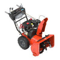
Step-by-step guide for installing the Sno-Thro attachment onto the unit.
Procedure for replacing shear bolts on the auger to prevent damage.
Instructions for the disassembly and assembly of the Sno-Thro attachment's gear case.
| Transmission | Single Speed |
|---|---|
| Deck Material | Steel |
| Mulching Capability | Yes |
| Bagging Capability | Yes |
| Side Discharge Capability | Yes |
| Starter Type | Recoil |
| Oil Capacity | 20 oz |
| Engine | Briggs & Stratton |
| Cutting Width | 21 inches |
| Warranty | 2 years |