1
O
N
6
5
4
3
2
D
I
P
88
7
GB - 11
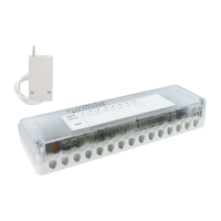
Fig. 1
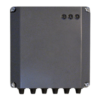
Fig. 2
installation
Warning!
Installation should be performed by a
qualifi ed technician.
Before connecting the receiver, discon-
nect the power supply.
Positioning
Install the wireless multizone kit well
away from electromagnetic fi elds (for ex-
ample: televisions, computers, refrigera-
tors, microwave ovens), as these could
a ect the operation of the device. Take
extra care when positioning the device
near lifts, stairways and metal wall struc-
tures, as these may have an isolating
e ect with regard to signal transmission
and reception.
Wall installation
- Undo the 5 screws and open the cover
(Fig. 1).
- Fix the device's base to the wall at the
chosen position, using the plugs and
screws supplied with the kit (Fig. 2).
The wireless multizone kit is a device for controlling up to 6 accessories including circu-
lation pumps, zone valves, etc., powered up to 230V.
Associating the wireless multizone kit with the radio receiver interfaces the device with
all products on the BUS BridgeNet® platform.
Warning!
Shut o power before working on the de-
vice.
Electrical connections
For greater safety, ask a qualifi ed techni-
cian to perform a thorough check of the
electrical system.
The manufacturer shall not be responsi-
ble for any damage caused by the ab-
sence of a suitable earthing system or
by the malfunctioning of the electricity
mains supply. Ensure that the electrical
system can provide the maximum pow-
er required by the module (as indicated
on the data plate). Ensure that the wires
have a suitable cross-sectional area of at
least 1.5 mm
2
.
Proper connection to an e cient earthing
system is essential for ensuring safe op-
eration of the device.
The power supply cable must be con-
nected to a 230 V-50 Hz network, while
observing the L-N poles and ensuring
connection to earth.
H05 V2V2-F
Important!
The connection to the mains must be per-
manent (not using a plug) and equipped
with a bipolar switch with a contact air
gap of at least 3 mm when open.
 Loading...