GB - 11
12
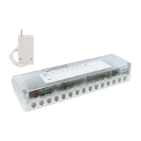
ON
LN
230V
LN
OUT 1
L
N
OUT 2
TB
BUS
TB
BUS
installation
Warning!
Installation should be performed by a quali-
fi ed technician.
Before connecting the receiver, disconnect
the power supply.
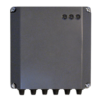
Positioning and installation
The device is designed for wall-mount-
ing.
After identifying a suitable wall, drill a
hole in it and insert one of the three wall
plugs provided, taking care not to dam-
age existing electrical wiring or piping,
and proceed as follows:
- hook the control unit onto the screw in-
serted into the wall beforehand (Fig. 1);
- remove the control unit cover by loos-
ening the four screws on the front (Fig.
2);
- mark the reference points for position-
ing the two wall plugs (Fig. 3), drill the
wall and insert the wall plugs;
- hang the control unit onto the wall and
insert the two fastening screws; before
tightening them, make sure that the en-
tire control unit rests against the wall
and is level, both horizontally and ver-
tically. If not, adjust the fastening screw
accordingly;
- close the control unit cover, tightening
the four screws on the front.
Fig. 1
Fig. 2
The 2-Zone management kit is a device that allows for operating 2 accessories, such as
circulator pumps, zone valves, etc., powered up to 230 V.
The device can be used with all products of the BUS BridgeNet® platform.
Fig. 3
 Loading...