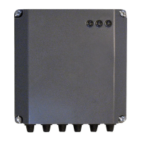
14 - GB
12
ON
12
ON
LN
230V OUT 1 OUT 2
TB
BUS
TB
BUS
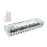
start-up
LED signals
GREEN LED (left)
o power supply OFF
steady power supply ON
fl ashing powered ON, board in manual mode
GREEN LED (central)
Light o BUS communication absent or not-OK
Steady light BUS communication present
Flashing light scanning or initialisation of BUS communication
RED LED (right)
Light o no operation error
Steady light presence of one or more operation errors
OUTPUT
CONTACTS
LOW-VOLTAGE
CONNECTIONS
LUMINOUS LEDS
ZONE ALLOCATION
MICRO-SWITCHES
BUS POWER SUPPLY
MICRO-SWITCHES
HIGH-VOLTAGE
CONNECTIONS
BUS NETWORK230 V POWER SUPPLY
Operation
The device activates the OUT1 and OUT2 outputs according to the “Output - Zone”
micro-switch shown on the previous page, depending on the presence of the heating
or cooling request generated by the corresponding zone.
 Loading...