EasyManua.ls Logo

Aritech AS2300 Series User Manual

Aritech AS2300 Series
14 pages
To Next Page IconTo Next Page
Page #1 background imageLoading...
Page #1 background image
AS2300 Series Addressable Loop Powered Sounders & Sounder-Beacons
Installation Instructions
8
6
5
(4) OUT+
(3) IN+/L+
(2) -/L-
(1)
a
7
S
a
b
(+)
L2
(-)
L1
a
b
c
1 2 3 4 5 6 7 8
1 2 3 4 5 6
NL
PT
EN
DE
IT
PL
LT
RU
SK
HU
EN
Installation instructions
Description
This document includes installation information for Aritech
AS2300 series addressable, loop powered sounders and
sounder/beacons.
AS2300 series sounders and beacons are designed for use in
Aritech analogue addressable fire systems running the 2000
Series protocol.
The sounders can be put into different operating modes.
To avoid sound interference between devices in the same
locality, the sounders are synchronised automatically.
Installation
The AS2300 series is polarity sensitive.
Drill out the cable entries and mounting holes as required on
the base. (See figure 1b.) A 20mm hole cutter must be used for
the deep base cable entries since attempting to knock them out
may crack the base.
Secure the base to the mounting surface with pan-head screws.
CAUTION: This product must be installed by qualified
personnel adhering to the TS54-14 specification and
any other applicable local authority regulations.
12
34
FR
Issue 3.0 (July 2010) 18-187110-3
Copyright © 2010 UTC Fire & Security BV. All Rights Reserved
UTC Fire & Security BV.
Kelvinstraat 7, NL- 6003DH Weert, The Netherlands.
+31 495 45 67 35 +31 495 55 00 42
Question and Answer IconNeed help?

Do you have a question about the Aritech AS2300 Series and is the answer not in the manual?

Aritech AS2300 Series Specifications

General IconGeneral
BrandAritech
ModelAS2300 Series
CategoryMarine Equipment
LanguageEnglish

Summary

Product Description

AS2300 Series Overview

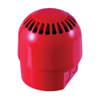
Details installation information for Aritech AS2300 series addressable, loop powered sounders and sounder-beacons.

Installation Guide

Safety and Regulatory Compliance

Product must be installed by qualified personnel adhering to TS54-14 and local authority regulations.

Mounting Base Preparation

Drill cable entries and mounting holes using a 20mm hole cutter for deep base entries.

Device Configuration and Operation

Electrical Connections

Details the wiring terminals for the AS2300 series, including L+, L-, and Earth connections.

Addressing

Explains the requirement for a unique numeric address (1-128) set via DIP switches.

Tone and Volume Selection

Describes how to set the device tone and volume using Tone Selector DIP switches.

Locking Mechanism

Instructions on how to lock and unlock the sounder onto its base for secure mounting.

Maintenance and Troubleshooting

Covers annual inspection, testing after installation, and common fault diagnosis.

Technical Specifications

Lists key technical data including supply voltage, current consumption, sound levels, and environmental ratings.

Certification and Approvals

Details compliance with standards like EN54-3 Type A and CPD certification bodies.

Address Settings Reference

DIP Switch Address Settings

Provides a comprehensive table showing DIP switch configurations for addresses 1 through 128.

Tone Setting Reference

Alarm Tones and DIP Switch Settings

Lists 32 different alarm tones with descriptions, application notes, and corresponding DIP switch settings.