2 / 4 P/N R466-5652 (EN) • REV A • ISS 07DEC23
Cautions
• Due to safety reasons, it is not allowed to install the
product in any location outside the building where the
corresponding control panel is placed (unless a proper
RS485 line insulation module is used). Network to network
insulation is required as no proper separation might
interact with alarm system signal integrity and cause
unexpected results.
• Any overhead lines are strictly prohibited.
• It is not recommended to use bottom cable duct directly
below touchscreen as installation cable signal may
interfere with RFID cards antenna field and could
decrease access cards identification range.
• Due to safety reasons, it is not allowed to wall-mount the
device higher that 2 meters from the floor, and in reach of
children.
• It is prohibited to perform any installation operations by
non-instructed person, in EN 62386 meaning.
Open the touchscreen, following the steps shown in Figure 3.
Unscrew the locking screw. Using a screwdriver, carefully prise
open the touchscreen near to the housing bottom corners.
Open the housing bottom first, top next.
Connect cable to touchscreen back plate. See also
“Connections” below.
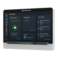
Figure 1: Touchscreen layout
(1) Presence sensor
(2) Touchscreen display
(3) Status LED bar
(4) Mifare card reader
Figure 2: Touchscreen base
(2) Pry-off tamper element
Cut out the knockouts for cable access if necessary. The
knockout positions are shown with arrows in Figure 5. Use
cable ties to fix cables in the cable passages if necessary.
Attach the base to mounting surface using provided screws,
including pry-off tamper screw, which fixes the pry-off tamper
element (Figure 2, item 2).
Tamper switch
The tamper switch must be inactive (closed) for the system to
work correctly. The tamper switch is sealed by mounting the
touchscreen onto the mounting plate.
DIP switch
DIP switch is located on the rear of the touchscreen (see
Figure 6, item 2) and is used for setting the touchscreen bus
termination (TERM) condition.
• SW1: TERM switch. To terminate the bus with the 120 Ω
built-in resistor, set DIP switch 1 to On, if required.
There must be no more than two TERM switches or links
set to On for any bus. Refer to Advisor Advanced
ATSx500A Installation and Programming Manual for
details on the data bus termination.
• SW2: Factory use only. SW2 must be in the Off position.
Caution: If the touchscreen is used with the standard
ATSx500A control panel hardware, which requires 470 Ω bus
termination, do not use built-in termination. Instead, connect a
470 Ω resistor in parallel with the data bus connection D+ and
D−. Set SW1 to the Off position.
Figure 6 shows the default DIP switch positions.
Figure 6: Touchscreen back view
Connecting control panel to touchscreen
Refer to Advisor Advanced Installation and Programming
Manual for instructions.
Connections
Figure 4 shows input and output wiring example.
• +12 V, 0 V: The touchscreen can be powered using the
bus “+” and “−” power from the control panel, if the
distance between the touchscreen and the control panel
does not exceed the maximum cable length given in
“Specifications” on page 3. Otherwise, the touchscreen
can be powered by AUX PWR from a DGP, or by an
auxiliary power supply. See “Specifications” on page 3 for
the power supply information.
• D+/D−: D+ is the data positive connection and D− is the
data negative connection of the data bus.
The touchscreen is connected to the ATS panel via the
RS485 data bus, up to 1.5 km from the control panel. It is
recommended to use two-pair twisted, shielded data cable
(WCAT 52/54). D+/D− should be connected by one
twisted wire pair. The shield of any bus cable must be
connected to system ground at one end only. The
touchscreen does not provide an earth connection for this
purpose. Isolate the wires and the shield of the cable
correctly to prevent any short circuit on the touchscreen.
• IN1: A request to exit button (normally open, momentary
push-button switch) can be connected across “IN” and
“0V” terminals. When pressed, this button controls the
request to exit function.
• IN2: For future use.
• OUT: Open collector output. For maximum allowed
current, see “Specifications” on page 3. Refer to Advisor
Advanced Installation and Programming Manual for
details.
Status LED bar indication
Multicolour LED bar can indicate the following statuses:
• Red On: Areas set
• Red flashing: Alarm condition active
• Orange On: Part set
• Orange flashing: System fault active / General alert
(EN 50131)
• Green On: System is ready to set
• Green flashing: Entry / exit time active
• Blue flash: Valid card presented / Access granted
• Off: Not ready to set / Armed display active
 Loading...