EasyManua.ls Logo

ARK Powerpack DA10W User Manual

ARK Powerpack DA10W
16 pages
To Next Page IconTo Next Page
Page #1 background imageLoading...
Page #1 background image
Important. Please read.
•Ensure Powerpack isolator switch is in the off
position while the battery is charging, except
when charging through the external terminals.
Keep clear of naked flame, spark or conductive
material, while the battery is charging.
Ensure that the Powerpack ventilation fan is
operating while the battery is charging.
Always turn the Powerpack isolator switch in off
position when the battery is not in use.
N15335
Part no. DA10W
Operating Instructions
Before operating this product
please read this manual thoroughly
and retain it for future reference
2012 Ark Corporation Pty Ltd
The original 12v smart charger battery box
Australian Innovation Patent No.2003100766
Australian Patent No.2003258369
Canadian Patent No.2538378
United States Patent No.7573229
United States Design Patent No. D495994
Canadian Registered Design No.104258
European Registered Design No.000076799-0001
Question and Answer IconNeed help?

Do you have a question about the ARK Powerpack DA10W and is the answer not in the manual?

ARK Powerpack DA10W Specifications

General IconGeneral
BrandARK
ModelPowerpack DA10W
CategoryPower Pack
LanguageEnglish

Summary

Operating Instructions

Identifying the parts

Powerpack adaptor

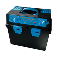
Details the powerpack adaptor unit.

Stainless steel brackets

Describes the stainless steel mounting brackets.

12V DC 10A accessory port with cover

Explains the 12V DC 10A accessory port and its cover.

Charger input with cover

Details the charger input port and its protective cover.

LED condition/charge indicator

Describes the LED indicator for battery status and charging.

Battery isolator switch

Explains the function of the battery isolator switch.

Positive high current terminal

Identifies the positive high current terminal connection.

Positive terminal cover

Describes the protective cover for the positive terminal.

Carry handle

Identifies the integrated carry handle.

Negative terminal cover

Describes the protective cover for the negative terminal.

Negative high current terminal

Identifies the negative high current terminal connection.

Ventilation fan

Identifies the ventilation fan.

Powerpack mounting

Step 1: Place the Powerpack

Instructions for placing the Powerpack in a suitable location.

Step 2: Mark bracket mounting holes

Instructions for marking and fastening mounting brackets.

Step 3: Locate Powerpack between brackets

Instructions for securing the Powerpack to the mounted brackets.

Connecting the battery

Step 1: Place the battery into the Powerpack base

Instructions for placing and securing the battery within the Powerpack.

Step 2: Ensure Powerpack switch isolator is off

Check that the isolator switch is off and adaptor is disconnected.

Step 3: Connect the positive red cable

Connect the positive battery cable to the positive terminal.

Step 4: Fasten the terminals securely

Instructions for securely fastening the battery terminals.

Step 5: Close the lid and fasten the latches

Instructions for closing the Powerpack lid and securing latches.

Connecting the load

Step 1: Connect to Powerpack high current terminals

Instructions for connecting a device to the high current terminals.

Step 2: Connect positive cable (red) of the device

Connect the device's positive cable to the Powerpack's positive terminal.

Step 3: Connect negative cable (black) of the device

Connect the device's negative cable to the Powerpack's negative terminal.

Step 4: Turn the isolator switch to the 'on' position

Activate the load connection by turning the isolator switch on.

Step 5: Accessory port protection

Information regarding the accessory port's 10A fuse and isolation switch.

Energy indicator

Step 1: Powerpack monitors energy level

The Powerpack monitors energy level via the LED indicator.

Step 2: View battery condition charge level

Press and hold the 'press to test' button to view battery status.

Using smartcharge

1 Charge cycle

Recovers a flat battery to peak voltage.

2 Bulk cycle

Tops up battery for extra capacity by raising voltage.

3 Boosting cycle

Peak charge maintained at 13.8V for maximum performance.

Smartcharge cycles

4 Resting cycle

Allows battery to consolidate after boosting, normalizing voltage.

5 Conditioning cycle

Maintains performance and prolongs battery life at 12.8V.

6 Re-waken cycle

Exercises battery to avoid sulphation build up.

Installing the Powerpack in a Dual Battery System

Charging the Battery using Solar Panels

Important Safety Information