EasyManua.ls Logo

Arlen Ness RAD III - User Manual

Arlen Ness RAD III
2 pages
Print Icon
To Next Page IconTo Next Page
Loading...
6050DublinBoulevard,Dublin,Ca.94568‐Technicalassistance:925.479.6379‐www.arlenness.com
RADIIIHANDLEBARCONTROLS
For96upHarleyDavidsonmodels
ThankyouforpurchasingthisArlenNessproduct.Webelievethatourproductsaretheverybestavailableandareengineered
toprovidealifetimeofuse.Basichandtoolsandaservicemanualforyouryearandmodelmotorcycleareallyouneedtocom
pletethisinstallation.
Parts:
1‐Brakemastercylinderassembly
1‐Clutchperchassembly
1‐Switchhousingset
1‐lowerleftswitchhousing(foraudioonly08748kitonly)
1‐Hardwarekit
1‐Instructions
1. Disconnectnegativebatterycable.Confirmthebikehasnopower.

2. RemoveOEMmirrorsandturnsignalsfromclutchperchandbrakemastercylinder.(ifsoequipped)

3. Startwiththethrottleside: 
(Allmodelsexcept08uptouring)Slackthrottlecablealltheway.Removeupperandlowerswitchhousing
screws.Lifttheupperswitchhousingupandrotateitforwardtogainaccesstothethrottlecableends.Remove
thecableendsfromthegripandremovegrip. 
(08uptouring)Removeupperandlowerswitchhousingscrews.Lifttheupperswitchhousingupandrotateitfor
ward,pushthelowerhousingdownandcarefullyremovegrip.

IMPORTANTNOTE:Duringthenextstepit’simportantnottogetbrakefluidonanypaintedsurfaces.Itwilldam
agepaint!Ifyougetbrakefluidonthepaintwashitoffimmediately.

4. Breakbanjoboltlooseatthemastercylinderthensnugitbackdownsoitdoesnotleak.Removemastercylinder
fromhandlebarandremovebrakeline.Securebrakelinepointingstraightupsoitdoesnotdrip.

5. (Allmodelsexcept08uptouring)Removethrottlecablesfromlowerswitchhousing.

6. NOTE:Duringthissteppaycloseattentiontohowthewiresarerouted,howthewiresaresecuredandbasically
howeverythingfitsinsideofthehousingsbeforedisassembly.Thiswillhelpduringreassembly.RemoveOEM
switchesandbuttonsfromOEMswitchhousingstheninstallthemintotheRADIIIhousing
sinreverseorderofre
moval.

7. (Allmodelsexcept08uptouring)Afteralltheswitchesandbuttonsareinstalledintonewswitchhousingsinstall
throttlecablesintolowerswitchhousing.Installthethrottlegripthenattachcablestoit.
(08uptouring)Afteralltheswitchesandbuttonsareinstalledintonewswitchhousingsinstallthethrottlegrip.

8. Positionswitchhousingsaroundgripandstartscrewsbutdonottighten.NOTE:Besurenottopinchanywires.

9. Attachbrakelinetonewmastercylinderusingnewbanjoboltandsealwashers(provided).Snugfornow.Attach
newmastercylindertohandlebarsmakingsuretoengagetabonlowerswitchhousingingrooveinmastercylin
der.Rotatecontroltodesiredpositionthenstartingwithtop,torqueboltsto67ft.lbs.
Question and Answer IconNeed help?

Do you have a question about the Arlen Ness RAD III and is the answer not in the manual?

Summary

Preparation and Throttle Side Disassembly

Initial Disconnection and Removal

Disconnect battery, remove mirrors, and turn signals.

Throttle Side Housing and Cable Removal

Remove throttle cables and master cylinder from the throttle side.

Throttle Side Reassembly and Master Cylinder Installation

Installing New Throttle Side Components

Install switches, cables, and master cylinder on the throttle side.

Securing Throttle Side Controls

Position switch housings and attach master cylinder to handlebars.

Clutch Side Disassembly and Reassembly

Clutch Side Housing and Cable Removal

Remove OEM switch housings, lever, and cable from the clutch side.

Installing New Clutch Side Components

Install new perch, lever, and cable, securing the switch housings.

Final Installation and Testing

Brake System Bleeding and Adjustment

Fill master cylinder, bleed brake system, and adjust controls.

Final Checks and Reassembly

Reconnect battery, test switches, and install mirrors/signals.

Overview

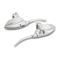
The RAD III Handlebar Controls are designed for 1996 and newer Harley Davidson models, providing a comprehensive solution for replacing or upgrading the motorcycle's handlebar controls. The product is manufactured by Arlen Ness, a company that emphasizes the quality and durability of its products, stating they are "engineered to provide a lifetime of use." The installation process is designed to be manageable with basic hand tools and a service manual for the specific motorcycle model.

Function Description:

The RAD III Handlebar Controls replace several key components of a motorcycle's handlebar system, including the brake master cylinder assembly, clutch perch assembly, and switch housing sets. These controls integrate the functions of braking, clutching, and operating various electrical switches and buttons. The system is designed to maintain or improve the ergonomic and functional aspects of the original equipment manufacturer (OEM) controls while offering an aftermarket aesthetic and potentially enhanced performance.

The controls facilitate the operation of the motorcycle by providing:

  • Braking: A new brake master cylinder assembly is included, which is responsible for converting the mechanical force from the brake lever into hydraulic pressure to actuate the front brake.
  • Clutching: A new clutch perch assembly is provided, which houses the clutch lever and cable mechanism, allowing the rider to disengage and engage the clutch.
  • Switch Operation: New switch housings are supplied to accommodate the OEM switches and buttons, ensuring that functions like turn signals, horn, and other electrical controls are accessible and operational. A specific lower left switch housing is available for audio-equipped models (part number 08-748 kit only).

Important Technical Specifications:

The manual provides several torque specifications crucial for proper installation and safe operation:

  • Switch Housing Screws (Throttle Side):
    • Initial tightening: Start screws but do not tighten.
    • Final torque: 6-7 ft.lbs. (for the bolts attaching the master cylinder to the handlebars, which also secure the switch housing).
    • Upper and lower switch housing screws: 35-45 in-lbs.
  • Banjo Bolt (Brake Master Cylinder):
    • Initial tightening: Snug down after breaking loose.
    • Final torque: 13-15 ft-lbs.
  • Switch Housing Screws (Clutch Side):
    • Initial tightening: Start screws but do not tighten.
    • Final torque: 6-7 ft.lbs. (for the bolts attaching the perch to the handlebars, which also secure the switch housing).
    • Upper and lower switch housing screws: 35-45 in-lbs.

These torque values are critical for ensuring that components are securely fastened without being over-tightened, which could lead to damage or failure. The use of new banjo bolts and seal washers is specified for the brake line attachment, highlighting the importance of proper sealing for the hydraulic system.

Usage Features:

The installation process outlines several usage features and considerations:

  • Compatibility: Designed for 1996 and newer Harley Davidson models. Specific instructions are provided for "08-up touring" models, indicating variations in installation steps for these bikes, particularly concerning throttle cable management.
  • Integration with OEM Components: The RAD III housings are designed to accept OEM switches and buttons, ensuring continuity of existing electrical functions. The process involves transferring these components from the original housings to the new ones.
  • Adjustability: The controls allow for rotation to a "desired position" before final torqueing, enabling riders to customize the ergonomic setup of their brake master cylinder and clutch perch for comfort and accessibility.
  • Throttle Cable Management: The system accommodates throttle cables, with specific instructions for slackening and reattaching them. For "08-up touring" models, a different method of removing the grip is described, involving pushing the lower housing down.
  • Clutch Cable Management: The clutch cable installation involves inserting the cable end into the new lever, retaining it with an anchor pin, and then installing the cable housing into the perch. A "slight bend" in the cable end is noted, with a caution against kinking the cable.
  • Brake Fluid Handling: The manual explicitly warns about the corrosive nature of brake fluid on painted surfaces, emphasizing the need to wash it off immediately if contact occurs. This highlights a critical safety and maintenance consideration during installation.
  • Clutch Adjustment: The installation process includes steps for adjusting the clutch according to OEM procedures, which involves removing the derby cover and loosening the clutch push rod adjusting screw. This step requires the bike to be standing straight up to prevent primary fluid spillage.
  • Battery Disconnection: The first step of the installation is to disconnect the negative battery cable, a standard safety precaution to prevent electrical shorts or accidental activation during work. Reconnecting the battery is the penultimate step, followed by testing all switches and buttons.

Maintenance Features:

While primarily an installation guide, the manual implicitly includes several maintenance-related features:

  • Component Replacement: The kit provides new components (master cylinder, clutch perch, switch housings), effectively replacing worn or damaged OEM parts.
  • Bleeding the Brake System: After installing the new master cylinder, the manual instructs the user to "Fill the master cylinder reservoir with the appropriate type of brake fluid then bleed system." This is a crucial maintenance step to ensure proper brake function and remove air from the hydraulic lines.
  • Clutch Adjustment: The requirement to adjust the clutch per OEM procedure after installation is a maintenance task that ensures the clutch operates correctly and prevents premature wear.
  • Wire Routing and Securing: The manual repeatedly advises paying "close attention to how the wires are routed, how the wires are secured and basically how everything fits inside of the housings before disassembly." This emphasizes the importance of proper wire management to prevent pinching, chafing, or damage, which could lead to electrical failures. This attention to detail during installation contributes to long-term reliability and reduces future maintenance needs.
  • Gasket/O-ring Replacement: When reinstalling the derby cover after clutch adjustment, the manual specifies using a "new gasket or o-ring." This ensures a proper seal and prevents fluid leaks, which is a key maintenance practice.
  • Post-Installation Testing: The final step of "Test all switches and buttons to confirm proper function" is a critical maintenance check to ensure all electrical components are working correctly after reassembly.

The RAD III Handlebar Controls are presented as a durable and high-quality aftermarket solution for Harley Davidson owners, designed for straightforward installation with clear instructions and important safety and maintenance considerations.

Arlen Ness RAD III Specifications

General IconGeneral
BrandArlen Ness
ModelRAD III
CategoryMotorcycle Accessories
LanguageEnglish